Electronic Whoopie Cushion
PE-017 in Pointless Electronics · By Onion Madder · Mess O' Pedals
Sit on it and it farts. A switch in the cushion fires one CD40106, which plays a low tone, chops it into a sputter, and lets it sag and die away, through a speaker. One chip, two transistors and a 9 V battery on a 13 by 21 board.
It is Pointless Electronics model PE-017. It does one thing, and it does it every time somebody sits down.
What you'll need
tap to expand / collapse
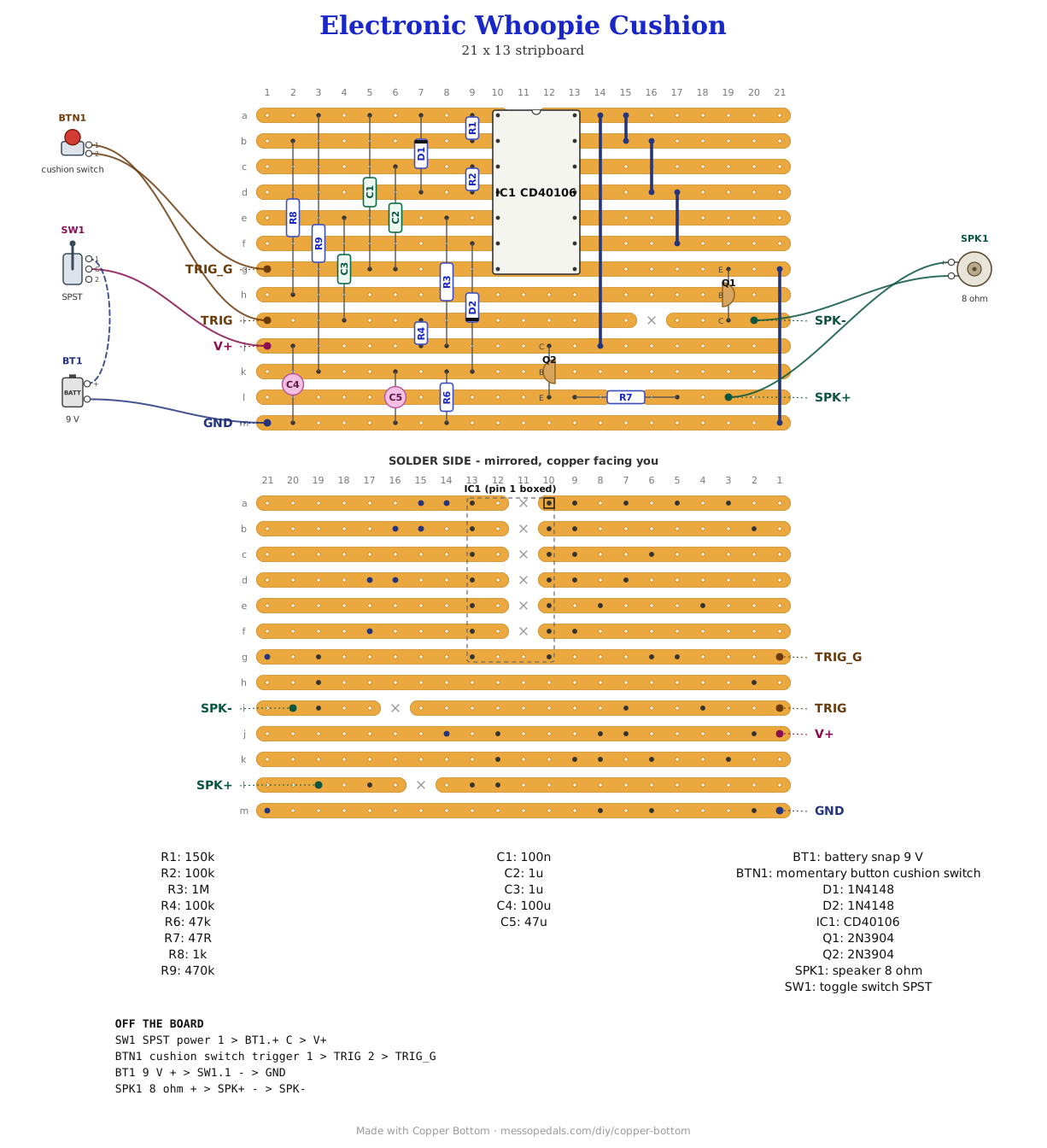
Seventeen parts on the board plus the chip and five links, and four off it. There is no R5: the numbering skips it.
- 1× CD40106 hex Schmitt inverter, DIP-14 (IC1) - spot it: fourteen legs, 40106 printed on top (CD40106BE, HEF40106). A 74HC14 has the same pinout but is not rated for 9 V, so check the print. It solders straight to the board, notch at the top
- 2× 2N3904 NPN transistors (Q1, Q2) - spot it: small black half-round body, 2N3904 on the flat face. Flat face toward you, legs down, they read E, B, C left to right, and the drawing labels every leg
- 2× 1N4148 diodes (D1, D2) - spot it: small glass body with a black band at one end. D1's band goes at the top, on strip a; D2's at the bottom, on strip k
- 1× 47 Ω resistor (R7) - spot it: bands yellow-violet-black. It carries the speaker current, about 130 mA in short pulses, so a 1/2 W one is the safe pick. It lies along strip l
- 1× 1K resistor (R8) - spot it: bands brown-black-red. Feeds Q1's base
- 1× 47K resistor (R6) - spot it: bands yellow-violet-orange. Drains the envelope
- 2× 100K resistors (R2, R4) - spot it: bands brown-black-yellow
- 1× 150K resistor (R1) - spot it: bands brown-green-yellow. Sets the tone
- 1× 470K resistor (R9) - spot it: bands yellow-violet-yellow. Bends the pitch as the fart dies
- 1× 1M resistor (R3) - spot it: bands brown-black-green. Sets how long the one-shot lasts
- 1× 0.1 µF ceramic (C1) - spot it: a small disc or blob marked
104. Sets the tone with R1 - 2× 1 µF caps (C2, C3) - spot it: ceramic or film marked
105, no stripe. C2 sets the flutter, C3 couples the cushion switch into the one-shot - 1× 47 µF electrolytic (C5) - spot it: a small can with a stripe down one side; the stripe leg is negative. Stripe down, on the ground strip m
- 1× 100 µF electrolytic (C4) - spot it: a bigger can, the supply reservoir. Stripe down, on strip m. Pick a slim one, about 5 mm across: R9's lead lands one hole to its right
- 5× wire links - offcuts of component leg. None of them runs under the chip
Off the board
- 1× switch for the cushion - anything that closes while somebody sits on it: two sheets of foil with foam between them, a pressure mat, or a momentary button under the cushion. One side to TRIG, the other to TRIG_G. Not tried yet, any of them
- 1× 8 Ω speaker - small is fine, 0.25 W or more. Plus to SPK+, minus to SPK-
- 1× 9 V battery and snap. Black to GND
- An SPST toggle for power, in the battery's red lead between the battery and the board's V+ pad. Every build on this shelf gets one, and this one needs it: switched on and waiting, it draws about 2 mA, which flattens a 9 V battery in about ten days
The layout file is the guide
Like every layout on this shelf, the build document for this one is the file itself: ↓ Download Electronic_Whoopie_Cushion.json - import it into Copper Bottom and the editor gives you the board picture, the placement walkthrough, the electrical checks and a printable build sheet, all from the same file. No coordinates are written out on this page on purpose: the editor is the viewer, and a number typed twice is a number that can drift.
J1, J2 and J3 tie the three spare inputs high, pins 13, 11 and 9, from the supply at pin 14. That holds their outputs low, which is why pin 8, an output, can share the ground strip with pin 7: the column beside the chip is cut on every strip but that one. Leave out J3 and pin 8 fights the ground strip.
Copper Bottom reports this one clean, and every connection in the netlist below is on the board.
The netlist
tap to expand / collapse
The netlist is written from the design, and the board was checked against it in Copper Bottom: every connection it names is on the board and nothing on the board is missing from it. TONE is the tone oscillator, FLUT the slow flutter that chops it, SHOT the one-shot the cushion fires, ENV the envelope cap that the one-shot fills and the speaker drains, and SW the cushion switch. OUT12 and OUT10 are the spare gates' outputs, which go nowhere.
The off-board wiring
Six pads leave the board: the cushion switch, the speaker and the supply.
| Pad | Goes to |
|---|---|
| TRIG / TRIG_G | The two sides of the cushion switch. Which way around does not matter |
| SPK+ / SPK- | The speaker's plus and minus |
| V+ | The power toggle; the toggle's other lug to the battery's red lead |
| GND | The battery's black lead |
Before you sit on it
Switch it on: it should stay silent. Then meter to ground. These numbers are the datasheet and the simulation, not off a built board.
| Meter | Expect |
|---|---|
| IC1 pin 14, the V+ pad | The battery, about 9 V |
| The TRIG pad, IC1 pin 5 | The full supply. TRIG drops to zero while the switch is closed |
| IC1 pin 6 | Zero. It goes high while somebody sits, for up to about a second |
| IC1 pins 8, 10 and 12 | Zero: the spare gates, inputs tied high |
| Strip k, C5's plus leg | Under a volt while waiting, about 8 V while sat on |
If it farts with nobody on it, the cushion switch is closed: meter TRIG. If it never makes a sound, check pin 6 goes high when you short TRIG to TRIG_G with a wire, then look at D2 and C5 and both transistors' legs.
How it works, in one breath
Three of the CD40106's six inverters do the work. The first, with R1 and C1, is the tone oscillator, and its output switches Q1, which pulls the speaker's minus side to ground. The second, with R2 and C2, is a flutter about 12 times a second, and through D1 it holds the tone oscillator still for half of every flutter, so the tone comes out in puffs. The third is the one-shot: closing the cushion switch kicks pin 5 low through C3, pin 6 goes high and fills C5 through D2, and R3 brings pin 5 back up in under a second. C5 is the envelope. Q2 follows it and feeds the speaker's plus side through R7, so the fart is as loud as C5 is full, and once the one-shot ends it fades out as C5 drains.
R9 runs from the envelope back into the tone oscillator, so the pitch sags as the envelope falls. In the simulation each puff is two pulses of the tone, about 17 ms apart while it is loud and about 30 ms apart as it dies, roughly 59 Hz falling to 33. Sat on and held, it plays loud for about a second and fades over another; a quick tap plays for as long as the tap and then fades. Whether that sounds like a fart is for the bench.
Things to try
None of these have been tried.
- Higher or lower. C1 sets the tone: 47 nF (
473) for a higher squeak, 0.22 µF (224) for a lower rumble - A wetter rasp. R2 sets the flutter: 47K makes it about twice as fast
- Longer. R3 sets the one-shot: 2.2M about doubles how long it plays loud when somebody stays sat down
The same circuit on a breadboard
tap to expand / collapse
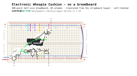
Want to hear it before you solder it? This is the layout file above moved onto a half-size breadboard, 30 columns by Copper Bottom's to breadboard button, in 38 steps with exact holes. It is a translation, not a copy: a strip and a breadboard column are different shapes, so every part is placed fresh and the stripboard's wire links are not needed.
Checked by the app, not built by me. Copper Bottom rebuilt the connections from these holes alone and compared them with the stripboard: all 56 terminals land on the same nets. Nobody has built this breadboard version.
Turn the board so the numbers climb left to right. Then A to E is the lower bank, F to J the upper, the top rails are above J and the bottom rails below A.
The semiconductors
| Step | Do |
|---|---|
| 1 | Seat IC1 (CD40106) across the center channel, notch to the LEFT: pin 1 in E8, pin 14 in F8. Pins 1-7 run E8 to E14; pins 8-14 run back F14 to F8. Anywhere in the same bank and column is the same point - E8 and A8 are both pin 1. |
| 2 | Diode D1 (1N4148): C11 to C8. The SECOND hole named gets the banded end - the cathode. Backwards, nothing works at all. |
| 3 | Diode D2 (1N4148): C13 to I16. |
| 4 | Transistor Q1 (2N3904): flat face toward you, legs E/B/C left to right into C15, C16, C17. The leg order is the package order, read with the flat face toward you and legs down. Check any device you are unsure of against its datasheet. |
| 5 | Transistor Q2 (2N3904): flat face toward you, legs E/B/C left to right into H15, H16, H17. |
Jumpers
| Step | Do |
|---|---|
| 6 | Jumper: A3 to A8 (C1.A to R1.A). |
| 7 | Jumper: J8 to the top + rail (IC1.14 to V+). |
| 8 | Jumper: J9 to the top + rail (IC1.13 to V+). |
| 9 | Jumper: J11 to the top + rail (IC1.11 to V+). |
| 10 | Jumper: J13 to the top + rail (IC1.9 to V+). |
| 11 | Jumper: J17 to the top + rail (Q2.C to V+). |
| 12 | Jumper: A14 to the bottom − rail (IC1.7 to GND). |
| 13 | Jumper: A15 to the bottom − rail (Q1.E to GND). |
| 14 | Jumper: J14 to the top − rail (IC1.8 to GND). |
| 15 | Jumper: A4 to F16 (C5.A to R6.A). |
| 16 | Jumper: tie the top + rail to the bottom + rail at the right-hand end, so they are one rail. |
| 17 | Jumper: tie the top − rail to the bottom − rail at the right-hand end, so they are one rail. |
Resistors
| Step | Do |
|---|---|
| 18 | Resistor R1 (150k): B8 to B9. |
| 19 | Resistor R2 (100k): C10 to B11. |
| 20 | Resistor R3 (1M): C12 to bottom + rail. |
| 21 | Resistor R4 (100k): C2 to bottom + rail. |
| 22 | Resistor R6 (47k): G16 to top − rail. |
| 23 | Resistor R7 (47R): I15 to I18. |
| 24 | Resistor R8 (1k): C9 to B16. |
| 25 | Resistor R9 (470k): D8 to J16. |
Ceramics and film
| Step | Do |
|---|---|
| 26 | Cap C1 (100n): C3 to bottom − rail. |
| 27 | Cap C2 (1u): B10 to bottom − rail. |
| 28 | Cap C3 (1u): B12 to B2. |
Electrolytics
| Step | Do |
|---|---|
| 29 | Cap C4 (100u): + leg into the bottom + rail, − leg into the bottom − rail. The stripe on the can marks the MINUS leg. Backwards, an electrolytic eventually vents. |
| 30 | Cap C5 (47u): + leg into C4, − leg into the bottom − rail. |
Off-board
| Step | Do |
|---|---|
| 31 | Wire for SPK-: into A17. This is where speaker - joins the board. |
| 32 | Wire for SPK+: into J18. This is where speaker + joins the board. |
| 33 | Wire for TRIG: into A2. This is where trigger switch / foil cushion lead 1 joins the board. |
| 34 | Wire for TRIG_G: into the bottom − rail. This is where trigger switch / foil cushion lead 2 joins the board. |
Power up
| Step | Do |
|---|---|
| 35 | GND - battery -: clip to the bottom − rail. |
| 36 | V+ - battery + via power switch: clip to the bottom + rail. |
| 37 | Before the battery: meter on continuity. rail to rail reads open, not a short A3 to A8 beeps (C1.A to R1.A) J8 to top + rail beeps (IC1.14 to V+) J9 to top + rail beeps (IC1.13 to V+) J11 to top + rail beeps (IC1.11 to V+) J13 to top + rail beeps (IC1.9 to V+) J17 to top + rail beeps (Q2.C to V+) A14 to bottom − rail beeps (IC1.7 to GND) A15 to bottom − rail beeps (Q1.E to GND) |
| 38 | Power on. |
Translated by Copper Bottom v1.7.29 from Electronic_Whoopie_Cushion.json.
A Schmitt inverter with a resistor and a cap is the classic one-chip oscillator, and a one-shot into an envelope cap is out of every CMOS cookbook. The layout and the words are mine, and so is anything wrong with them.