MFOS Box Supply
±12V and a separate 9V from one AC wall wart · A 7812, a 7912 and a 78L09 · By Onion Madder · Mess O' Pedals
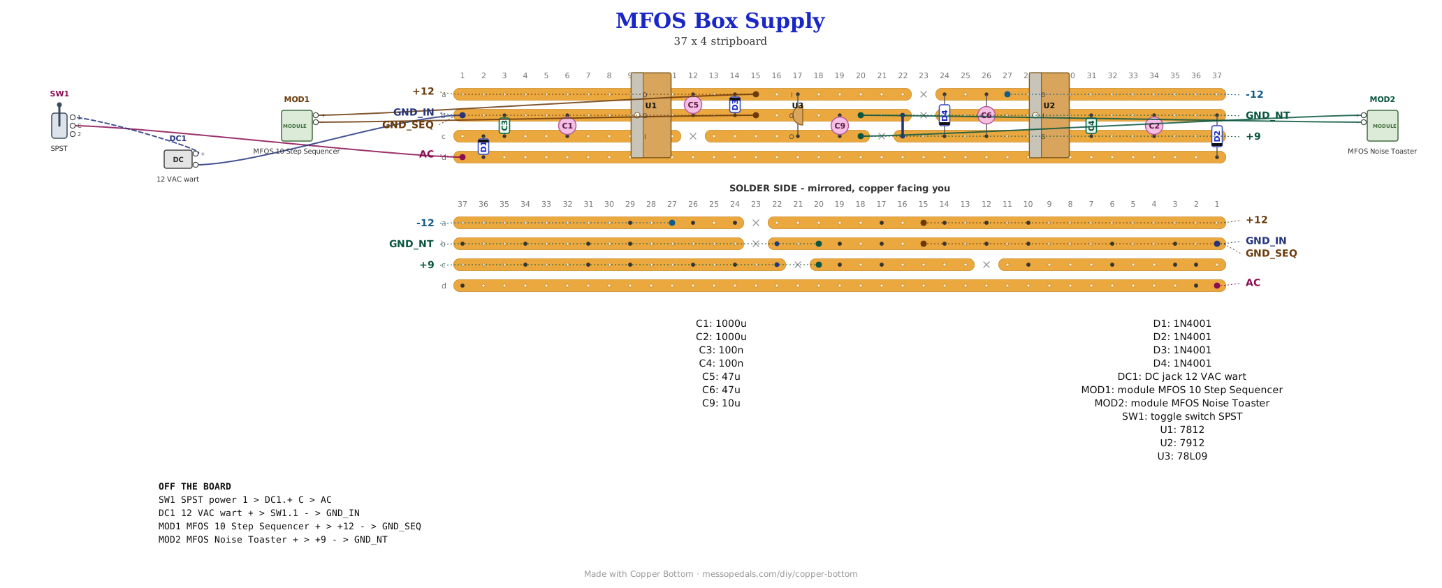
Two Music From Outer Space boards going into one box, wanting two different supplies: the 10 Step Sequencer runs on 12V bipolar, plus and minus, and the Noise Toaster runs on 9V. This board makes all three rails from one 12 VAC wall wart, with a power switch in the lead. The sequencer gets +12V, -12V and a ground; the Toaster gets its own regulated 9V and a ground, wired where its battery clip used to go. Fifteen parts, four cuts, and three regulators standing in a row.
What you'll need
tap to expand / collapse
- 1× 7812 (U1), the +12V regulator. Spot it: TO-220, a black body with a metal tab and three legs, 7812 printed on the face. Printed face toward you: IN, GND, OUT. The tab is ground
- 1× 7912 (U2), the -12V regulator. Same package, and not the same legs: printed face toward you it is GND, IN, OUT, and the tab is its input, not ground. See the heatsink note under the wiring
- 1× 78L09 (U3), the 9V regulator. Spot it: TO-92, the small half-round body like a transistor. Flat face toward you: OUT, GND, IN - the reverse of the big ones
- 4× 1N4001 (D1 to D4). Spot it: black body, silver band at the cathode end. D1 and D2 are the rectifiers, D3 and D4 the output clamps. All four stand up. Any 1N4001 to 1N4007 works
- 2× 1000 µF, 35V electrolytic (C1, C2), the reservoirs. Spot it: the two big cans, about 12.5 mm across. The stripe marks the negative leg. C2 goes in the way that looks backwards: its positive leg is on ground and its stripe on the negative rail. The drawing is right
- 2× 47 µF, 25V electrolytic (C5 on +12, C6 on -12). C6 is the other one that looks backwards: positive leg to ground. The 7912 needs it - its datasheet will not promise a stable output without a cap there
- 1× 10 µF electrolytic, 16V or more (C9), on the 9V output
- 2× 100 nF ceramic (C3, C4), marked
104, one on each regulator input - 1× link of solid wire (J1)
- 1× stripboard, 4 strips × 37 holes or larger
Off the board
- 1× 12 VAC wall wart, 300 mA or more (a 500 mA one is plenty). It has to be an AC one: the label says AC output or shows a wavy line. A DC wart will not work - it only fills one side
- 1× DC jack to match the wart's plug, usually 2.1 mm. AC has no polarity, so it does not matter which way round the plug is wired
- 1× SPST toggle, the power switch, in the jack's tip lead
- Five wires to the boards: three to the sequencer (+12, -12, ground), two to the Noise Toaster (+9, ground)
- Optional: two clip-on TO-220 heatsinks. Not needed at these currents, but see the note below before sharing one
The layout file is the guide
Like the rest of this shelf, the build document for this one is the file itself: ↓ Download MFOS_Box_Supply.json - import it into Copper Bottom and the editor gives you the board picture, the placement walkthrough, the electrical checks and a printable build sheet, all from the same file. No coordinates are written out on this page on purpose: the editor is the viewer, and a number typed twice is a number that can drift.
Leave room for the big cans. Copper Bottom draws every electrolytic the same small size, so it cannot see that C1 and C2 are 12.5 mm across. The layout keeps the two columns either side of each one empty for them. Do not fill those holes with anything else.
The netlist
Quoted verbatim from the layout file. It was written from the board, so checking the board against it can only pass - what it is for is carrying the circuit somewhere else, and telling you what each strip is supposed to be doing while you stare at it.
The off-board wiring
Seven pads leave the board: two for the wall wart, three for the sequencer, two for the Noise Toaster.
| Pad | Goes to |
|---|---|
| AC | The power switch's middle lug. The switch's other lug goes to the DC jack's tip |
| GND_IN | The DC jack's sleeve. This lead of the wall wart becomes the ground for everything in the box |
| +12 / -12 / GND_SEQ | The 10 Step Sequencer's +12V, -12V and ground. Twist the three together on the way |
| +9 / GND_NT | The Noise Toaster, where its battery clip's red and black leads went. Take the clip off; nothing else on that board changes |
The 7912's tab is its input. The 7812's tab is ground and the 7912's is the raw negative rail, so bolting the two to one bare heatsink, or to a metal box, shorts the negative side to ground. Give each its own clip-on heatsink, or use a mica pad and an insulating washer on the 7912. At the currents two MFOS boards draw, neither needs a heatsink at all.
Before the boards go on
Power the supply on its own first, with nothing connected to the output pads, and meter each rail to GND:
- +12 should read about 11.5 to 12.5V, and -12 about -11.5 to -12.5V
- +9 should read about 8.6 to 9.4V
- If a rail reads near zero, check that regulator's legs against the list above first. The 7812, the 7912 and the 78L09 all have different leg orders, and one in backwards is the likeliest fault on this board
- If the negative rail is missing entirely and the wart is running warm, check the wart is AC. A DC one fills only one side
Then connect both boards, switch on, and check +12 again with everything running. If it holds, the supply has the headroom it needs.
How it works, in one breath
One lead of the wall wart is ground and the other swings about 17V either side of it, sixty times a second. D1 lets the positive half through into C1 and D2 lets the negative half through into C2, so the two big caps charge to about +16V and -16V and hold there between peaks. The 7812 and 7912 turn those into steady +12V and -12V; each wants about 2V more than its output at the bottom of the ripple, and with 1000 µF and a hundred milliamps or so of load it gets that. The 9V comes off the regulated +12V rather than the raw one, so the 78L09 only burns off 3V and the Toaster never sees any ripple at all. D3 and D4 do nothing in normal running. They are there for the moment of switching on, when one regulator can come up faster than the other and a load across both rails drags the slow one past ground; the diode catches it.
Things to try
- If +12 sags or hums with both boards running, the sequencer is pulling more than this was drawn for. A 2200 µF, 35V for C1 halves the ripple, but it is a bigger can and needs more room than the layout leaves
- A power LED. An LED and a 4K7 in series from +12 to ground, off the board, lights whenever the box is on
- A third rail. Another 78L-series regulator off +12 the same way the 78L09 is - a 78L05 for 5V logic - with its own 10 µF on the output
No circuit to credit: the half-wave split supply is the one every regulator datasheet draws. The layout is Onion Madder's, drawn in Copper Bottom. The two boards it feeds are Ray Wilson's, from Music From Outer Space - see the MFOS rebuilds.