Power Starve
A voltage starve that cannot burn out its pot · An LM317 on five strips · By Onion Madder · Mess O' Pedals
Every circuit bender has starved a toy: drop its supply voltage and the sound goes slow, thin, wrong and interesting. The usual way is a pot in series with the battery, and the usual way dies the usual death. The whole toy's current runs through the pot's carbon track, the track is rated for a tenth of a watt, and at the low-resistance end - exactly where the sound gets good - it cooks. This board puts an LM317 between the supply and the toy instead. The pot only sets the regulator's reference, a few milliamps through it ever, and the regulator carries the toy with its own current limit and thermal shutdown standing behind it. Short the output and it folds back instead of smoking. Eight parts, one cut, and small enough to go inside the toy.
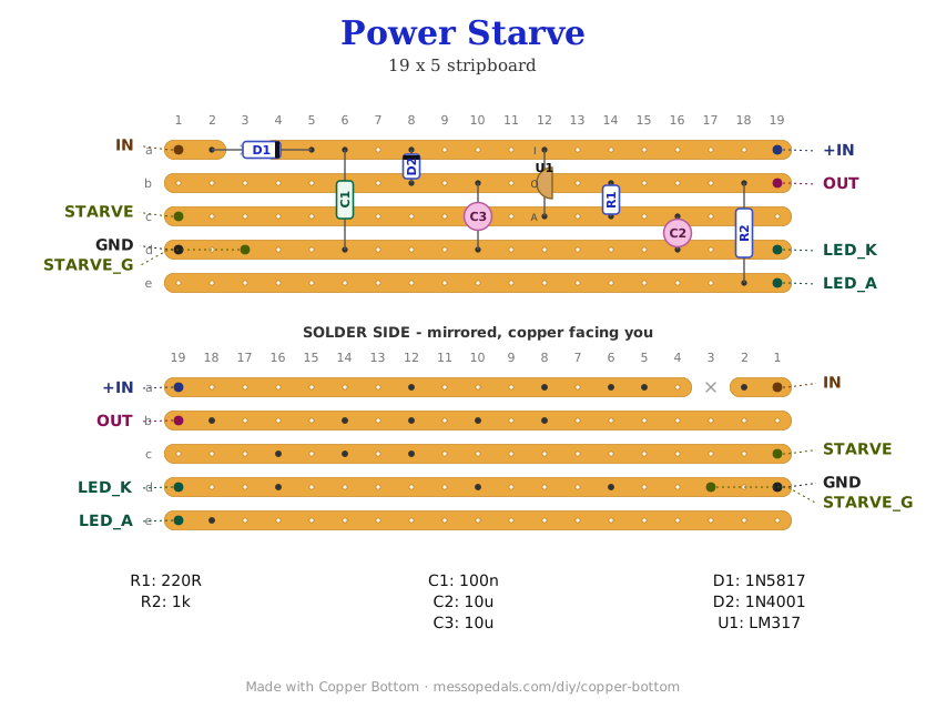
What you'll need
tap to expand / collapse
- 1× LM317 adjustable regulator, TO-220 (U1) - spot it: LM317 or LM317T on the face, three legs and a metal tab with a hole. The legs are ADJ, OUT, IN left to right with the lettering toward you, and the tab is OUT. The little TO-92 LM317L works too for a toy under 100 mA, and stands in the same three holes
- 1× clip-on heatsink for the TO-220. Not optional on a hungry toy: a 9V supply starved to 2V at 200 mA is 1.4 watts of heat in that tab
- 1× 1N5817 Schottky (D1) - spot it: small black body, band at the cathode end. Reverse-polarity protection; the band points along the strip toward the regulator
- 1× 1N4001 rectifier (D2) - spot it: black body, band at the cathode end. Any 1N400x works. It stands up on this board with the band at the top
- 1× 220R (red-red-brown, R1) - the top of the divider that sets the voltage. Stands up. 240R is the datasheet's value and works the same
- 1× 1K (brown-black-red, R2) - the panel LED's resistor
- 1× 100n ceramic (104, C1) - across the regulator's input
- 2× 10 µF electrolytic (C2, C3) - one on the ADJ pin so the knob sweeps smoothly, one on the output for stability. Spot it: the stripe marks the negative leg, and both stripes go to the ground strip
- 1× stripboard, 5 strips × 19 holes or larger. No links
Off the board
- 1× B1K linear pot, the starve knob - spot it: B is linear, and linear is right here because the voltage tracks the knob one to one. B1K spans 1.25V to about 6.9V, the whole knob live on a 9V battery. Use a B2K if you feed it from a 12V supply; a B5K works but the top half of its travel does nothing
- 1× SPDT toggle, the bypass - straight through for the toy at full voltage, because the regulator cannot give it the last two volts of the supply
- 1× LED, any color, panel mounted. The 1K on the board is its resistor. It dims as you starve, which is the whole reason it is there
- A supply, 4.5V to 15V - a 9V battery, or a DC jack and a wall wart. Whatever the toy was running on, this box goes between it and the toy
- A way in and a way out: two DC jacks, or flying leads straight into the toy's battery contacts if it lives inside
The regulator, from the front
 LM317, TO-220, lettering toward you, legs down
        _______
       |  tab  |   tab = OUT
       |_______|
        |  |  |
        A  O  I      ADJ   OUT   IN
Copper Bottom draws every three-leg regulator as a TO-92 and labels the legs A, O, I in that order. That is the LM317's real order too, so the drawing is right; only the body is the wrong shape. Stand the TO-220 on its legs with the tab facing the board's top edge, clip the heatsink on, and check it against the netlist before you power it.
The layout file is the guide
Like the 555 theremin and the Opto Duet, the build document for this one is the file itself: ↓ Download Power_Starve.json - import it into Copper Bottom and the editor gives you the board picture, the placement walkthrough, the electrical checks and a printable build sheet, all from the same file. No coordinates are written out on this page on purpose: the editor is the viewer, and a number typed twice is a number that can drift.
The netlist
Quoted verbatim from the layout file. It was written from the board, so checking the board against it can only pass - what it is for is carrying the circuit somewhere else, and telling you what each strip is supposed to be doing while you stare at it.
The off-board wiring
Eight pads leave the board. Three of them are the bypass toggle's.
| Pad | Goes to |
|---|---|
| IN / GND | The supply, 4.5V to 15V, center positive if it is a jack. IN goes through the Schottky, so a backwards plug does nothing at all |
| +IN | The supply after the diode. This is the bypass toggle's DIRECT throw |
| OUT | The starved supply. This is the bypass toggle's STARVE throw. The toggle's common goes to the toy's + - so the toy sees either the regulator or the raw supply, never both |
| STARVE / STARVE_G | The starve pot. Wiper to STARVE, one outer lug to STARVE_G, the third lug empty - or strapped to the wiper, so a scratchy wiper cannot open the divider for an instant. Which lug you use sets which way the knob starves |
| LED_A / LED_K | The panel LED, long leg to LED_A, short leg to LED_K. Its resistor is on the board. It is fed from the starved rail, so it dims as you turn the knob down and goes out before the toy does |
The toy's ground and the board's ground are the same wire. The starve is in the + leg only. If the toy has its own power switch, leave it in the + lead between OUT and the toy and it still works as a power switch.
How it works, in one breath
An LM317 holds exactly 1.25V between its OUT and ADJ pins, whatever the load. Put a 220R between them and 1.25V across 220R is about 5.7 mA flowing down through the pot to ground - and the output voltage is whatever that current makes across the pot, plus the 1.25. So OUT = 1.25 × (1 + pot ÷ 220): 1.25V with the knob at zero, about 3.5V a quarter of the way up a B1K, 6.9V at the top. The knob never carries more than those few milliamps. The toy's current, however much it is, goes through the regulator's tab.
That is the whole trick, and the rest is housekeeping. C1 keeps the regulator from oscillating when the battery's leads are long; C3 does the same on the output; C2 on the ADJ pin makes the knob sweep like a fade instead of a staircase; D2 lets the output caps discharge through a diode rather than backwards through the regulator when the supply is yanked; and D1 means the one thing every starve box eventually has done to it, a plug the wrong way round, does nothing.
Two limits, both the regulator's. It cannot go below 1.25V, which does not matter - almost every toy is dead by 2V. And it cannot get closer than about 2V to the supply, which does: on a 9V battery the knob tops out near 7V. That is what the bypass toggle is for. Flip it and the toy is on the raw supply through nothing but the Schottky.
Heat, unmeasured. Everything the toy does not get, the regulator turns into heat: supply minus output, times the toy's current. A 9V toy starved to 2V at 100 mA is 0.7W, warm; at 300 mA it is 2.1W and wants the heatsink. If it gets too hot it shuts itself down and comes back when it cools, which is the LM317 being polite rather than the board being wrong.
Things to try
- Build it into the toy. Five by nineteen fits behind most battery doors. Feed IN from the battery contacts, OUT to where the battery + used to go, the pot and the toggle through the case, and the toy has a starve knob for life
- Two toys, one box. Nothing here cares what is on the output. A second OUT wire from the same pad starves both at once, as long as the regulator can carry the pair
- A starve footswitch. Put the bypass on a footswitch instead of a toggle: stamp for the starved sound, stamp again for full voltage
- Voltage-controlled starve. Anything that can pull the ADJ pin around moves the output: a photocell in place of the pot is a starve you play with your hand in the light, the same trick as the Opto Duet's eyes
Circuit from the LM317 datasheet's adjustable regulator, which is the “proper” starve every bending forum eventually recommends once a pot has burned. The bypass toggle, the LED and the layout are Onion Madder's, drawn in Copper Bottom.
↓ Same box, jacks on top (PDF)
The second sheet keeps every control where this one has it and moves the jacks - power and audio - to the top wall, so the cables leave upward. Two ways to drill one box; pick one.
The LED at the top, the starve knob, the bypass toggle, DC in and DC out along the bottom. Or build it into the toy and drill nothing but a knob hole.
Print at 100% / “Actual size”, never “Fit to page” - check the bar measures exactly 4″ before you touch a drill. The face is 66 by 121 mm but only 42 mm of it is drillable once the lid lip is clear.
Nobody has drilled this one yet. The hole sizes come from the layout file; where they sit is this format applied to it. Offer the sheet up to the box and check it against your own parts before you make a hole.