Tube Meter
A 6E2 magic-eye tube as a level meter: a green bar that closes when it hears you · By Onion Madder · Mess O' Pedals
A 6E2 is a tuning indicator from the age of valve radios: a little triode and a fluorescent target in one glass bottle, and a green bar on the side of the glass that closes up as the grid goes negative. Feed the grid the rectified envelope of a signal and it becomes a level meter that glows, the way a VU needle never will. This board is everything around the tube: a transistor to lift a line-level signal up to something the tube can see, a diode and two resistors to turn that into a negative voltage, a regulator for the heater, and two resistors on the high-voltage side. The high voltage itself comes from a small boost module that lives off the board, because a 250 V supply is not something to draw on stripboard for fun.
Before you start
tap to expand / collapse
This build has 150 to 250 volts DC in it, and that can kill you. The boost module makes it from 12 V, so the wall wart is not the danger; the module's output is, and so is its output capacitor, which holds that charge after the power is off. The rules, none of them optional:
Never touch the board, the tube socket or the module with the power on. Not to adjust, not to probe with a finger, not to steady it. Switch off, then wait, then measure.
After switching off, measure the HV pad to ground with a meter rated for 300 V before you touch anything. If it reads more than a few volts, discharge it: a 100K resistor on insulated leads from HV+ to GND, held for ten seconds, then measure again. Do this every time. Not most times.
One hand. When you must work near it live - you should not need to - keep the other hand in your pocket, so a shock cannot cross your chest.
Everything high-voltage is insulated and mounted. The board on standoffs, never loose in a metal box. The three high-voltage wires in insulation rated for it, with heat-shrink over every joint at the socket. The module fixed down. No bare copper anywhere near the lid.
Strips b and d stay empty. That is what keeps the 250 V a full strip away from the 12 V and from your fingers on the solder side. Do not put a part or a wire there because it looks convenient. Keep the solder side clean: a whisker of solder from strip a to strip b is a whisker at 250 V.
Drill before you solder, and blow the box out. Aluminum swarf is conductive, and this is the one board on the site where a stray chip can arc.
The tube gets hot. Not dangerously, but you will not want your thumb on the glass, and neither will the paint on the box near the window.
What you'll need
tap to expand / collapse
- 1× 2N3904 NPN transistor, TO-92 - spot it: 2N3904 on the flat face, legs E, B, C left to right with the flat toward you
- 1× 7806 voltage regulator, TO-220, plus a small clip-on heatsink - spot it: the big three-legged tab package, 7806 or L7806 on the face, legs I, G, O left to right with the face toward you. Not the little TO-92 78L06: the heater draws more than it can carry. It stands on its legs on the board
- 1× 1N5817 Schottky - spot it: black body, silver band. Reverse-polarity protection on the 12 V
- 1× 1N4148 signal diode - spot it: tiny glass body, black band. The clamp that makes the envelope negative
- 2× 220K (red-red-yellow), 1/4 W or better - the anode load, two in series so each drops half the voltage. These two are the only parts on the high-voltage side
- 1× 100K (brown-black-yellow) and 1× 22K (red-red-orange) - the transistor's bias divider
- 1× 10K (brown-black-orange) collector load, 1× 470R (yellow-violet-brown) emitter
- 1× 1M (brown-black-green) and 1× 2M2 (red-red-green) - the envelope's attack and its bleed
- 4× 100nF ceramic (104) - input coupling, collector coupling, the envelope hold, and the regulator's input
- 2× 100 µF electrolytic - one on the 12 V rail, one on the heater rail. Spot it: the stripe marks the negative leg
- 1× stripboard, 10 strips × 26 holes or larger. No links on this one
Off the board
- 1× 6E2 magic-eye tube and a noval (9-pin) socket, chassis mount - spot it: a glass tube about 20 mm across with a flat green window down one side and nine pins in a circle with a gap. Sold as the EM84 / 6FG6 equivalent, usually from China, often with a socket. The socket is the thing you wire to; the tube plugs into it
- 1× high-voltage boost module, 12 V in, 150 to 250 V DC out, adjustable - spot it: the small boards sold for nixie clocks, a coil, a MOSFET, a trimmer and a tall capacitor, often marked NCH6100HV or 170V. Set it to 200 V before it goes anywhere near the tube, with the tube unplugged
- 1× 100K linear pot (B100K) - the sensitivity. All three lugs
- 1× 12 V DC supply, 1 A, center positive, and a DC jack. Not a battery: the heater alone takes about a quarter of an amp
- 1× toggle for power, 1× 3.5 mm jack for the input
- Insulated wire rated for the voltage (ordinary hookup wire of 300 V rating is fine), heat-shrink for the socket, standoffs for the board, a 100K resistor on insulated leads for discharging, and a meter rated for at least 300 V DC. These are not optional
- An upright 125B with a window filed in the face - the template further down
The tube, pin by pin
The 6E2 is sold as the equivalent of the EM84 and the 6FG6, and these are the EM84 base connections, from the EM84 data. I could not lay hands on a 6E2 sheet of its own, so check the sheet that comes with your tube before you wire the socket - if it disagrees with this table, the sheet wins. Pins count clockwise from the gap, looking at the pins.
| Pin | What it is | Wire it to |
|---|---|---|
| 1 | Grid | The GRID pad. The negative envelope |
| 2 | Internal connection | Nothing. Do not connect |
| 3 | Cathode | GND |
| 4 | Heater | The HEATER pad, 6 V |
| 5 | Heater | GND |
| 6 | Target, the fluorescent screen | The TARGET pad. High voltage |
| 7 | Deflection electrode | The ANODE pad, with pin 9 - they are tied together at the socket. High voltage |
| 8 | Internal connection | Nothing. Do not connect |
| 9 | Anode, the triode plate | The ANODE pad. High voltage |
The numbers the design leans on, from the EM84 data: heater 6.3 V at 0.21 A; supply 250 V with a 470K anode load; the bar goes from fully open to fully closed as the grid goes from 0 to about −22 V; and the target wants at least 150 V before it glows at all. The 6E2 is said to be more sensitive than the EM84, which is why the sensitivity pot exists.
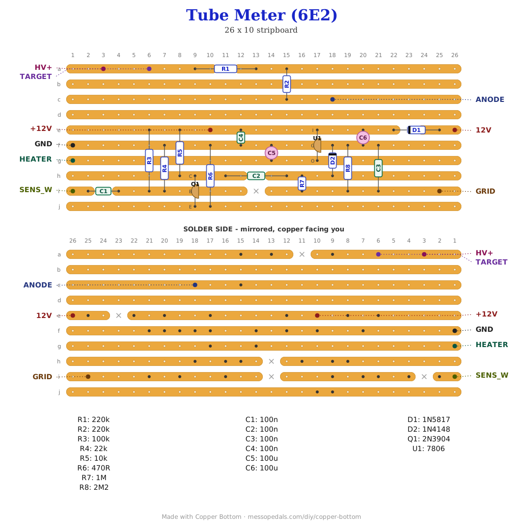
The layout file is the guide
Like the 555 theremin and the Opto Duet, the build document for this one is the file itself: ↓ Download Tube_Meter.json - import it into Copper Bottom and the editor gives you the board picture, the placement walkthrough, the electrical checks and a printable build sheet, all from the same file. One thing the editor does not know: it draws the 7806 as a small three-legged part, and it is a TO-220 with a tab. Same three legs, same order, bigger body.
The netlist
Quoted verbatim from the layout file. It was written from the board, so checking the board against it can only pass - what it is for is carrying the circuit somewhere else, and telling you what each strip is supposed to be doing while you stare at it.
The off-board wiring
Nine pads leave the board. Three of them carry the high voltage and are marked.
| Pad | Goes to |
|---|---|
| 12V / GND | The DC jack, 12 V, through the power toggle. GND also takes the input jack sleeve, the pot's lug 3, the tube's pins 3 and 5, and the boost module's negative |
| HV+ | The boost module's positive output. Its input comes from the same 12 V as the board, after the power toggle. High voltage |
| TARGET | Tube pin 6. High voltage |
| ANODE | Tube pins 9 and 7, tied together at the socket. High voltage |
| HEATER | Tube pin 4. Pin 5 goes to GND |
| GRID | Tube pin 1 |
| SENS_W | The sensitivity pot's wiper. Lug 1 to the input jack tip, lug 3 to GND |
| +12V | Nothing. A test point on the protected rail, and it tells Copper Bottom's checker that strip is a supply |
The three high-voltage wires are the ones to fuss over. Heat-shrink over every joint at the socket, no bare wire anywhere, and route them away from the low-voltage side and the lid. A 300 V rated hookup wire is the normal stuff; what matters is that none of it is bare.
How it works, in one breath
The tube's bar is controlled by its grid: at 0 V the bar is open, and as the grid goes negative the bar closes, fully by about −22 V. So the job of the board is to turn a signal into a negative DC voltage that follows its loudness. A line-level signal is a volt or two, which is not enough to move the bar far, so it goes into a 2N3904 common-emitter stage first: 100K and 22K set the bias, 10K in the collector and 470R in the emitter give a gain of about twenty, and it swings most of the 12 V rail.
That swing goes through a 100n to a node with a 1N4148 clamp on it, anode on the node and cathode to ground. The diode will not let the node rise above about 0.6 V, so every positive peak is held there and the whole waveform is pushed down: its negative peaks now sit at roughly minus the peak-to-peak swing. A 1M and a 100n average that into a DC level and a 2M2 bleeds it away when the signal stops, so the bar closes fast and opens slowly, which is what a meter should do. The sensitivity pot sets how loud is loud.
On the high-voltage side there is almost nothing: the target goes straight to the boost module's output, and the triode anode goes there through 440K of load, two 220K in series so neither resistor sees the whole 250 V across it. The heater is 6 V from the 7806, a hair under its 6.3 V rating, well within what a heater tolerates, and the regulator earns its heatsink at a quarter of an amp.
Unbuilt, and these are the bench numbers. How far the bar travels at a given input, which is the transistor's gain against the tube's sensitivity, and the reason the pot exists; whether 6 V is enough heater for a bright display or the regulator wants swapping for a 6.3 V source; where the boost module is best set between 150 and 250 V for brightness against tube life; and how warm the 7806 runs. None of it is dangerous to find out if the rules above are followed. All of it is unknown until someone does.
Print at 100% / “Actual size”, never “Fit to page” - check the bar measures exactly 4″ before you touch a drill. The face is 66 by 121 mm but only 42 mm of it is drillable once the lid lip is clear.
Nobody has drilled this one yet. Measure your own tube's glass before you file the window; not every 6E2 is the same bottle. Offer the sheet up to the box and check it against your parts before you make a hole.
Tube data from the EM84 datasheet, which the 6E2 is sold as equivalent to; the clamp detector is the way every magic-eye meter has driven its grid since the tubes were new. The transistor stage, the split anode load, the guard strips, the layout and the box are Onion Madder's, drawn in Copper Bottom.