Battery Breakout
Two 9V batteries, one power header · Test a module before the case arrives · Takes no HP · By Onion Madder · Mess O' Pedals
Every module on this shelf wants ±12 V on a ten-pin header, and until the case or the bus board exists there is nothing to plug one into. This is the way to bring a module up anyway: two 9V batteries in series make ±9 V, and this little board puts it on the same 2×5 header the modules take. A battery cannot be plugged in backwards at the wall, cannot push much current into a short on a fresh board, and floats free of everything else on the bench - and every module here has a 1N5817 in each rail anyway. It takes no HP and has no panel; it sits on the bench at the other end of a ribbon.
What you'll need
tap to expand / collapse
On the board, counted from the layout file:
- 2× 4k7 (yellow-violet-red; R1, R2) - one for each rail LED, lying along its strip across a cut
- 2× 10u electrolytic (C1 to C2) - spot it: the stripe marks the negative leg
- 2× LED, any color (D1, D2) - spot it: the long leg is the anode. D1 lights for the + battery, D2 for the - one
- 2 wire links (J1 to J2) - solid core, tinned
- 1× 2×5 pin header, plain, 0.1″ - the Eurorack power connector. spot it: ten square pins in two rows. Not the shrouded kind; a shroud is 20 mm long and would cover the neighboring strips
- Stripboard, 5 strips × 14 holes or larger
Off the board
- 2× 9V battery and battery snap - red lead plus, black lead minus
- 1× DPDT toggle, the power switch, one pole per battery - an on-on DPDT works, using the middle lug and one end of each pole
- 1× 10-pin to 10-pin Eurorack power ribbon - not a 16-pin one, see the note below
What it is
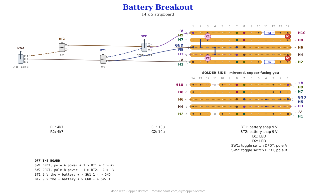
Five strips, one rail each. The header stands with its pins down the strips, the way every module here takes it, so each pin pair lands on one strip: +V on top for the +12 pins, three joined ground strips in the middle, and -V on the bottom strip, H1 and H2, the red stripe end. A 10 µF steadies each rail. An LED on each rail, through a 4.7K on its own island past a cut, lights only if that battery is in and the right way around, so the check before the ribbon goes on is two lights. Off the board, one DPDT toggle switches both rails together, so a module never sees one rail without the other.
Use a 10-pin to 10-pin ribbon. A 16-pin plug can sit on a 10-pin header one row out, and that puts the rails on the wrong pins. Nothing taller than a flat link stands under the ribbon's socket, so it pushes straight down.
The layout file is the guide
As on every stripboard guide here, the build document is the file itself: ↓ Download Battery_Breakout.json - import it into Copper Bottom and the editor gives you the board picture, the placement walkthrough, the electrical checks and a printable build sheet, all from the same file. No coordinates are written out on this page on purpose: the editor is the viewer, and a number typed twice is a number that can drift.
The netlist
Quoted verbatim from the layout file. It was written from the design, so the editor's check that the board matches it compares two separate records - what it is for is carrying the circuit somewhere else, and telling you what each strip is supposed to be doing while you stare at it. The three rails are named for what they carry.
The off-board wiring
13 pads leave the board. Ten of them are the power header.
| Pad | Goes to |
|---|---|
| +V | The DPDT's first pole, common lug. That pole's other lug takes the first battery's red lead |
| -V | The DPDT's second pole, common lug. That pole's other lug takes the second battery's black lead |
| GND | The middle of the two batteries: the first battery's black lead and the second battery's red lead, joined here |
| H1 … H10 | The power header itself. Nothing leaves the board here; the ribbon plugs onto it. H1 and H2, the red stripe, are -V, on the bottom strip |
Bringing a module up on it
Will ±9 V run them? Yes, for a first test. The Hive, Cicada, Grub and Spider run their CMOS from their own 78L05 at 5 V, which wants about 7 V in; 9 V less the module's 1N5817 is plenty, so the pitches should be where they would be in the rack. The TL072 and TL074 stages on every module swing a little less than they will on ±12 V. The Envelope uses only the positive rail.
- Before any power, meter the module: resistance across each rail to ground and between the two rails. Near zero is a short; find it first. Then diode-test each 1N5817: about 0.2 to 0.3 V one way, open the other
- Switch the breakout on with nothing plugged in. Both LEDs lit means both batteries are in the right way around
- First power-up with the meter in series in one battery lead, on its milliamp range. Tens of milliamps is right; hundreds means switch off and look for the short
- Measure the rails on the module: about +8.7 and -8.7 V after its diodes, and 5.0 V on the 78L05 where there is one
- Listen with the amp turned all the way down. Rack level is around ten volts peak to peak, far hotter than a guitar
How it works, in one breath
Two batteries in series, and the point between them is ground: the top of one is +9 V and the bottom of the other is -9 V. That is all a bipolar supply is. Each LED runs from its rail to ground through 4.7K, about 1.5 mA, enough to see and not enough to matter to the batteries; a module or two draws tens of milliamps, so a fresh pair is many hours of bench time. All of that is arithmetic, not measured.
Things to try
- Two modules at once. A ribbon with several sockets on it feeds more than one; keep the total to a few tens of milliamps and watch the batteries
- Darker LEDs. 10K instead of 4.7K halves their current if the batteries matter more than the lights
- Retire it. Once the case or the bus board is up, this is still the board to bring a brand-new module up on before it goes near the rest
Two batteries in series as a split supply is as old as op-amps. The header follows Doepfer's bus standard, as every module here does. Drawn and checked in Copper Bottom.