Eurorack Bus Board
One DC adapter, twelve modules · +12, -12 and +5 from a single supply · Bolts to the case, takes no HP · By Onion Madder · Mess O' Pedals
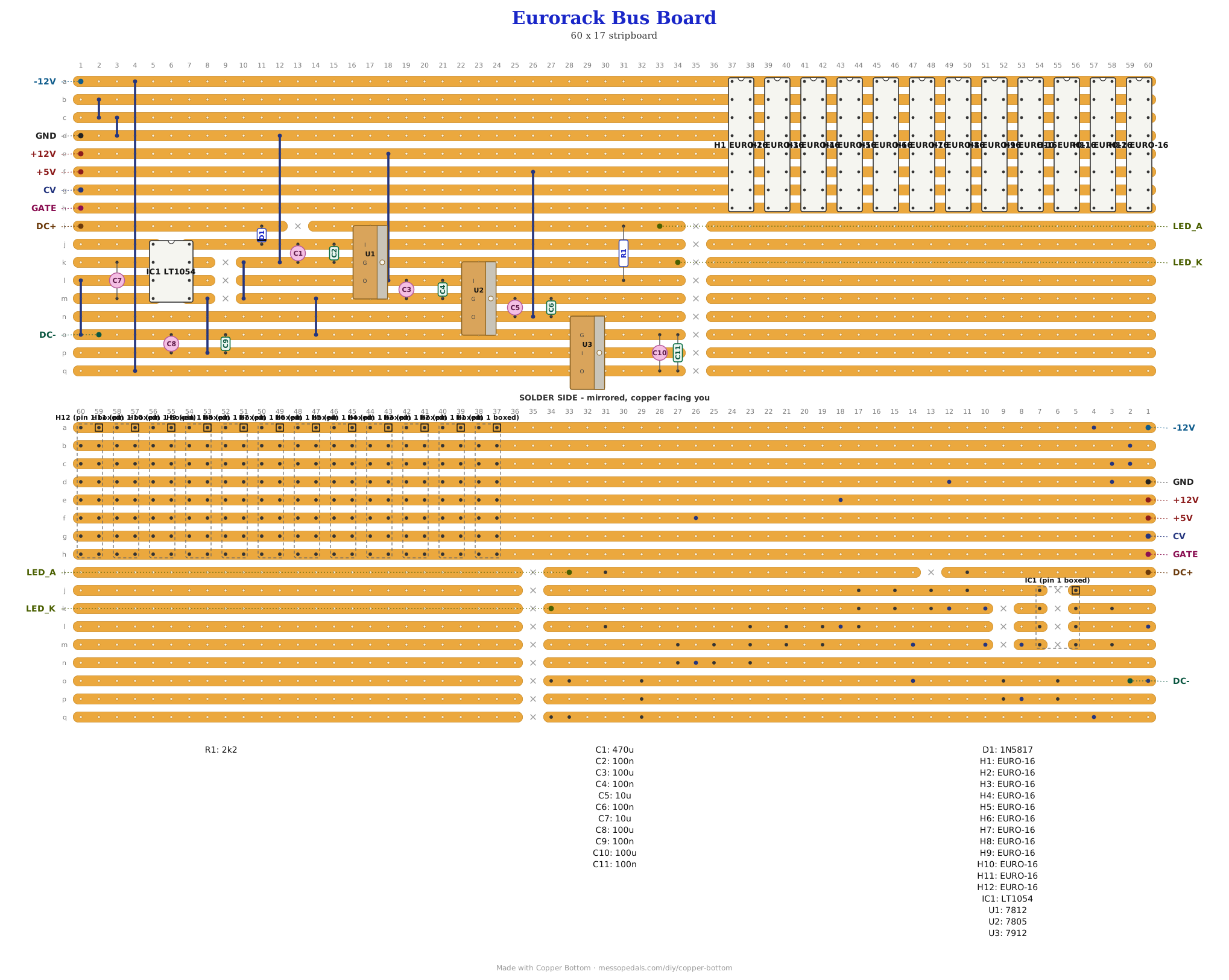
Every module on this shelf wants ±12 V on a ten- or sixteen-pin header, and nothing here makes it. This board does: one regulated DC adapter in, three rails out to twelve modules. A 7812 makes the +12, an LT1054 charge pump turns the raw supply upside down for a 7912 to make the -12, and a 7805 takes the +5 off the +12. It is not a module - it takes no HP and has no panel. It bolts to the case, and the modules plug into it.
What you'll need
tap to expand / collapse
On the board, counted from the layout file:
- 1× LT1054 switched-capacitor voltage converter, 8-pin DIP - the charge pump that makes the negative rail. spot it: LT1054 printed on top, notch marks pin 1. Not an ICL7660: same job, about twice the current (IC1)
- 12× EURO-16 bus headers, 2×8 plain pin header, 0.1″ - one per module, twelve of them side by side. spot it: sixteen square pins in two rows. Not the shrouded kind: a shroud is about four columns wide and twelve would not fit on a 160 mm board. Plain is safe here because every module already carries a diode on each rail, so a cable fitted backwards does nothing (H1 to H12)
- 1× 2k2 (red-red-red; R1)
- 5× 100n ceramic disc (104; C2, C4, C6, C9, C11)
- 3× 100u electrolytic (C3, C8, C10) - spot it: the stripe marks the negative leg
- 2× 10u electrolytic (C5, C7) - spot it: the stripe marks the negative leg
- 1× 470u electrolytic (C1) - spot it: the stripe marks the negative leg
- 1× 1N5817 Schottky, the reverse-polarity diode - spot it: a fat black body, band toward the cathode (D1)
- 1× 7812 1 A positive regulator, TO-220 - spot it: the big three-legged tab package. Printed face toward you and the tab away, the legs are IN, GND, OUT, and the tab is GROUND. That is the REVERSE of a little 78L05 (U1)
- 1× 7805 1 A 5 V regulator, TO-220 - same package and same leg order as the 7812: IN, GND, OUT with the printed face toward you, tab is GROUND. This is the one that certainly wants a heatsink (U2)
- 1× 7912 1 A NEGATIVE regulator, TO-220 - and its legs are not the 7812 mirrored: printed face toward you they are GND, IN, OUT, and the tab is its INPUT, not ground. Do not bolt it to the same bare heatsink as the 7812 (U3)
- 10 wire links (J1 to J10) - solid core, tinned
- Stripboard, 17 strips × 60 holes or larger
Off the board
- 1× DC jack, panel or chassis mount, for a regulated 15 V (or 13.8 to 14 V) adapter at 1 A or better, center positive - read the supply note above before buying one
- 1× panel LED, the power indicator - any color. The 2k2 that feeds it is on the board, and it runs off the +12 rail, so it tells you about that rail and no other
- 2× TO-220 heatsinks, clip-on, for the 7805 and whichever of the other two you load heavily - NOT one heatsink shared between the 7812 and the 7912
- 1× Eurorack case or rails to bolt it to, and standoffs - it is a bus board, not a module, so it needs no panel and no HP
- 12× Eurorack power cables, whichever of 10- and 16-pin your modules take
What it is, and the shape stripboard gives it
The board is two halves that barely touch. The top eight strips are the bus and carry no cut anywhere, because that is exactly what a 2×8 header lands on: its sixteen pins are eight pairs, and each pair sits on one strip, so eight strips is eight rails and every header is two columns wide. Twelve of them butt up against each other along those strips. The bottom nine strips are the supply, and they stop at column 34 - cut there, so nothing raw or unregulated runs under the headers.
The rails, top to bottom, are -12, ground, ground, ground, +12, +5, CV, Gate. The three grounds are one net, joined by two links. That is the Doepfer arrangement, and the top three rows of it are the part to read carefully - see the sourcing note below.
One thing about the layout is worth knowing before you place a part: a TO-220 is four holes wide. Standing on its legs down three strips, a 7812 covers four rows and nearly two columns - it reaches a row past its outer legs at each end - where a little TO-92 sits inside its own leg span. The script that drew this board refuses to write if anything else lands under one, which is how the first draft got caught with four capacitors and a resistor inside a regulator.
The layout file is the guide
As on every stripboard guide here, the build document is the file itself: ↓ Download Eurorack_Bus_Board.json - import it into Copper Bottom and the editor gives you the board picture, the placement walkthrough, the electrical checks and a printable build sheet, all from the same file. No coordinates are written out on this page on purpose: the editor is the viewer, and a number typed twice is a number that can drift.
The netlist
Quoted verbatim from the layout file. It was written from the board, so checking the board against it can only pass - what it is for is carrying the circuit somewhere else, and telling you what each strip is supposed to be doing while you stare at it. The eight bus rails are named for what they carry, and the supply's own nodes for the part that makes them.
The off-board wiring
10 pads leave the board. Six of those are test points and the indicator LED; nothing on the bus leaves the board, because the headers are the bus.
| Pad | Goes to |
|---|---|
| DC+, DC- | The DC jack. Tip and sleeve. A regulated adapter, center positive; the 1N5817 on the board means a backwards plug does nothing rather than everything |
| LED_A, LED_K | The panel power LED, long leg and short. It runs off the +12 rail through the 2k2 on the board, so it lights whenever the positive side is up - it says nothing about the other two rails, which is what the test points are for |
| +12V, -12V, +5V, GND | Test points, one per rail. Nothing leaves the board here. Meter all three against GND with nothing plugged in, before you connect a single module - that is the whole reason they exist, and they also tell the editor's checker that those strips are supplies |
| CV, GATE | The legacy CV and gate buses. They reach every header and nothing else on this board, so they are a bus waiting for something to drive them rather than an output. Doepfer's assignment for those two rows is inference here, not a table - see the supply note |
The supply, and the one thing to get right before you buy anything
The adapter has to be REGULATED. Not a preference. The LT1054 sits on the raw rail, about a third of a volt below whatever the adapter puts out, and its absolute maximum supply is 15 V. An unregulated brick marked 15 V sits near 20 V with nothing drawing from it, which kills the chip the first time you plug it in. A regulated 15 V switching adapter is inside spec with very little to spare, so a regulated 13.8 or 14 V adapter is the safer buy and costs nothing: at the 20 to 30 mA these modules pull on the negative rail the charge pump drops well under its rated volt, so the 7912 still sees about -13 V and it only wants about a volt of headroom. One amp or better, center positive.
Twelve volts in does not work, which is why the adapter is the size it is. Invert 12 V and you get about -11, and a 7912 cannot make -12 out of that - the negative rail would land wherever the load left it.
The current budget, from the six modules' own parts. A TL072 idles at about 1.4 mA per rail, a 78L05 pushes about 3 mA into ground off the +12, and CMOS gets a 2 mA allowance:
| Modules | +12 V | -12 V |
|---|---|---|
| the six on this shelf | 45 mA | 10 mA |
| twelve | 90 mA | 20 mA |
| sixteen | 119 mA | 26 mA |
Those boards are almost nothing on -12 - one TL072 each - which is why a single charge pump is comfortably enough, and why it is an LT1054 rather than the usual ICL7660: about 100 mA against 45, a real ground rather than a virtual midpoint, and it sags instead of shorting when you ask for more.
A BOUGHT module is the unknown. Nothing on this shelf pulls much from the negative rail; a commercial filter or a stereo output stage can pull 30 to 80 mA on its own and eat the whole inverter. The way to spot it is on the module's own page - makers publish the two numbers - and the way to catch it after the fact is to meter the -12 rail with everything plugged in. If it sags, that is the charge pump running out, not a fault on this board.
Do not bolt the 7812 and the 7912 to one bare heatsink. On a positive regulator the metal tab is GROUND; on a 7912 the tab is its INPUT. Sharing bare metal shorts the raw negative rail to ground. They want separate heatsinks or insulating washers. The 7805 is the one that definitely needs a heatsink whatever else you do: it drops the whole 7 V from the +12 rail as heat, which is about 0.7 W at 100 mA.
The +5, CV and Gate rows are inference, not a table. Pins 1 to 10 are read off six real modules, which all agree: the red-stripe pair is -12, then six grounds, then +12. Doepfer keeps the sixteen-pin assignment in an image rather than a table, so the top three rows here come from two independent sources agreeing on the physical order. They are drawn as +5, CV and Gate on that basis. A module's own documentation wins over this page. Nothing on this board drives CV or Gate - they reach the headers and their pads and stop - so the only row that puts a voltage anywhere on inference is the +5, and if you own nothing that wants it, leave the 7805 out.
How it works, in one breath
The adapter comes in through a 1N5817 onto the raw rail, where a 470 µF holds it up. The 7812 takes that down to +12, the 7805 takes the +12 down to +5, and both are the ordinary three-leg arrangement with a reservoir and a 100 n at each output. The interesting one is the negative side: the LT1054 is a charge pump, so it has no inductor and makes no noise floor of its own - it charges a 10 µF capacitor across the raw rail, then flips that capacitor over and dumps it into a reservoir the other way up, twenty-five thousand times a second. That gives about -13 V, rough, and the 7912 turns it into a clean -12.
Three of the chip's pins are meant to be left open on a plain inverter - FB, OSC and VREF - and that is what the two orphan findings in the editor are. They are stubs on purpose, and the layout gets them for free: the chip's own cut column splits each of its four rows into a left pin and a right pin, and one more cut keeps the right-hand ones off the rails those rows carry further along the board. No strip is wasted making an open pin open.
Things to try
- Leave the 7805 out. If nothing you own wants the +5 rail - and nothing on this shelf does - do not fit it. It is the one part that certainly needs a heatsink, and the row it feeds is the one whose pin assignment is inference
- Ten-pin headers instead. The same eight strips take a 2×5 header on the lower five rails, so a board built for 10-pin cables is this one with the top three rows unused. Everything on this shelf is 10-pin
- A second LED on the negative rail. The power LED here says the +12 is up and nothing else. A 2k2 and an LED from ground to -12 would say the other half is too, which on a board with a charge pump in it is the half worth watching
- More headers. A header is two columns; the pattern repeats until the board runs out. Sixteen still fits inside the budget above, on the same regulators
The supply is the ordinary three-terminal regulator arrangement out of the 7812 and 7912 datasheets, and the inverter is the LT1054's own basic voltage-inverter figure. The rail assignment is Doepfer's bus standard, verified on the lower ten pins against my own modules and inferred on the upper six. Drawn and checked in Copper Bottom.