Bug Bus
One supply for the whole Bug Box · Six outputs, no chip · By Onion Madder · Mess O' Pedals
The six boards in the Bug Box - the Hive, Dragonfly, Cicada, Grub, Firefly and Hornet - each want a 9V and a ground. Put them in one box and you do not want six wires twisted onto one jack. This board is the thing in between: one wall wart in, six supplies out, with a master switch, a power light, and a little insulation between the boards so that one oscillator's current does not turn up in another one's pitch. No chip. Fifteen parts, eight cuts, and most of them are the same five columns six times over.
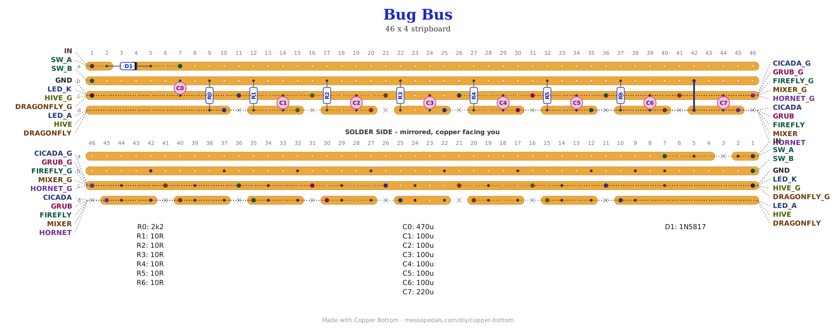
What you'll need
tap to expand / collapse
- 1× 1N5817 Schottky (D1) - spot it: small black body, band at the cathode end. Reverse-polarity protection; the band points along the strip away from the IN pad
- 1× 470 µF electrolytic (C0), the bulk cap on the switched rail. 220 µF to 1000 µF all fine. Spot it: the biggest can; the stripe marks the negative leg, and it goes to the ground strip
- 5× 100 µF electrolytic (C1 to C5), one per filtered output. Stripe to the ground strip on every one
- 1× 220 µF electrolytic (C6), on the amp output. Another 100 µF works; bigger is better here
- 5× 10R (brown-black-black, R1 to R5), one per filtered output. They stand up
- 1× 2K2 (red-red-red, R0) - the power LED's resistor. It stands up too
- 1× link of solid wire (J1), the amp output's feed
- 1× stripboard, 4 strips × 41 holes or larger - a strip cut off the long edge of a bigger board is exactly this shape
Off the board
- 1× SPST toggle, the master power switch. Or a wire between its two pads if the box has no switch
- 1× LED, any color, the power light. Its resistor is on the board
- A DC jack and a 9V wall wart, center positive. 12V at most, because the Hornet's LM386 tops out there. Not a battery: see below
- Twelve wires, six pairs, one pair per bug board. Twist each pair
The layout file is the guide
Like the 555 theremin and the Opto Duet, the build document for this one is the file itself: ↓ Download Bug_Bus.json - import it into Copper Bottom and the editor gives you the board picture, the placement walkthrough, the electrical checks and a printable build sheet, all from the same file. No coordinates are written out on this page on purpose: the editor is the viewer, and a number typed twice is a number that can drift.
The netlist
Quoted verbatim from the layout file. It was written from the board, so checking the board against it can only pass - what it is for is carrying the circuit somewhere else, and telling you what each strip is supposed to be doing while you stare at it.
The off-board wiring
Eighteen pads leave the board. Twelve of them are the six boards, a pair each, named for who they feed.
| Pad | Goes to |
|---|---|
| IN / GND | The DC jack, tip and sleeve. A 9V wall wart, center positive, 12V at most. IN goes through the Schottky, so a backwards plug does nothing |
| SW_A / SW_B | The master toggle, one side each. It sits in the + leg after the diode; everything on the board is off when it is off. No toggle in the box: wire the two pads together |
| LED_A / LED_K | The power LED, long leg to LED_A, short leg to LED_K. Its 2K2 is on the board. It is on the switched rail, so it says what the toggle says |
| HIVE / HIVE_G, DRAGONFLY / DRAGONFLY_G, CICADA / CICADA_G, GRUB / GRUB_G, FIREFLY / FIREFLY_G | Five boards, one pair each. The named pad to that board's V+, the _G beside it to that board's ground, and twist the pair. Each is the switched rail through its own 10R and 100 µF, so each board sits on its own filtered rail |
| HORNET / HORNET_G | The amp. The switched rail straight through, no resistor, with the biggest cap. An LM386 pulls hundreds of milliamps on peaks, and even 10R would sag it |
The five filtered outputs are identical, so the names are a convenience for wiring, not an assignment the copper cares about - swap the Grub onto the Cicada's pair and nothing changes. The one that is not interchangeable is the Hornet's. A board with its own power switch keeps it; this toggle is upstream of all of them.
How it works, in one breath
It is a bus, so mostly it is copper. The one idea on it is the 10R and 100 µF on each output. Every oscillator on the Bug Box draws its current in pulses at its own pitch, and on a shared rail those pulses become a little ripple that every other board sees on its supply - and a CMOS oscillator's pitch follows its supply. Ten ohms and a hundred microfarads is a low-pass filter with a corner near 160 Hz: the ripple mostly stays on the board that made it, and at the few milliamps a CMOS board draws, the 10R drops almost nothing. The ground side is handled by geometry: every board's ground wire comes back to this strip through its own pad, so the grounds meet in one place and no board's return current runs through another board's wire.
This is a wall-wart project, not a battery one. On their own these boards already ask more of a 9V battery than it likes - they do not play right on one for long - and six of them together, with an LM386 driving a speaker, is somewhere between 50 and 300 mA. A sagging shared rail drags every pitch on the box down together. So: a DC jack and a 9V wall wart, and the Schottky makes a wrong-polarity wart harmless. 12V at most, because the Hornet's LM386 tops out there.
Things to try
- A seventh channel. The pattern is five columns: the series part, a gap, the cap, the output pad, a cut with the ground pad above it. Open the file, add five columns, repeat it. The Mosquito is the bug not in the box yet
- Starve the whole box. Put the Power Starve between the supply and IN, and one knob drags every bug down together. Or put it on one output and starve one bug at a time
- A switch per board. An SPST in any OUT wire mutes that board and saves its current. The cap on that output stays charged, so it comes back without a thump
- Bigger filters for the low ones. A slow LFO voice draws its current in slow gulps; if a neighbor still breathes with it, 47R and 220 µF on that output moves the corner down to 15 Hz. The drop across 47R is still under half a volt at 10 mA
No circuit to credit: a diode, a switch, a capacitor and six RC filters, which is what every multi-board box eventually grows. The layout is Onion Madder's, drawn in Copper Bottom for the Bug Box.