Wire a 3PDT Footswitch for True Bypass
Nine lugs, seven wires and a jumper · By Onion Madder · Mess O' Pedals
True bypass means that when the pedal is off, the input jack is wired straight to the output jack and the board is out of the picture. A 3PDT footswitch does that and switches an LED at the same time. This page is the wiring for any pedal: all the board needs is an input, an output and a ground.
What you'll need
tap to expand / collapse
- 1× 3PDT latching footswitch - spot it: a metal stomp button on a threaded bushing, with nine flat solder lugs underneath in three rows of three. It clicks and stays. It wants a 12 mm hole
- 1× LED - spot it: the long leg is the positive one, and the short leg is on the side with the flat on the rim
- 1× resistor for the LED, if the board does not already have one - 4.7K is a good start on 9 V, bands yellow-violet-red. Without one the LED burns out
- Hookup wire, and a short offcut for the jumper
- Multimeter with a continuity beep - spot it: the dial position with a little speaker or sound-wave symbol
1 Find the columns
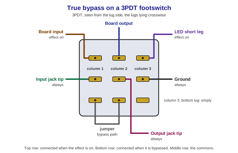
Hold the switch with the lugs facing you. Each lug is a flat blade. Turn the switch until the blades lie crosswise, wide side toward you, and they make three columns of three. Each column is one switch: the middle lug is the common, and it connects to the top lug in one position of the button and the bottom lug in the other.
Do not trust the turn alone. Set the meter to beep, put one probe on a middle lug and the other on the lug above it, and click the button: it should beep in one position and not the other. The lug next to it sideways should never beep. If a sideways neighbor beeps, turn the switch a quarter turn and try again.
Which end you call the top does not matter. It only matters that all three columns are wired the same way up.
2 Wire it
Solder the jumper first, while nothing is in the way. Then the rest.
| Column | Top lug (effect on) | Middle lug | Bottom lug (bypassed) |
|---|---|---|---|
| 1 | The board's input | Input jack tip | A jumper across to column 2's bottom lug |
| 2 | The board's output | Output jack tip | The jumper from column 1's bottom lug |
| 3 | The LED's short leg | Ground | Empty |
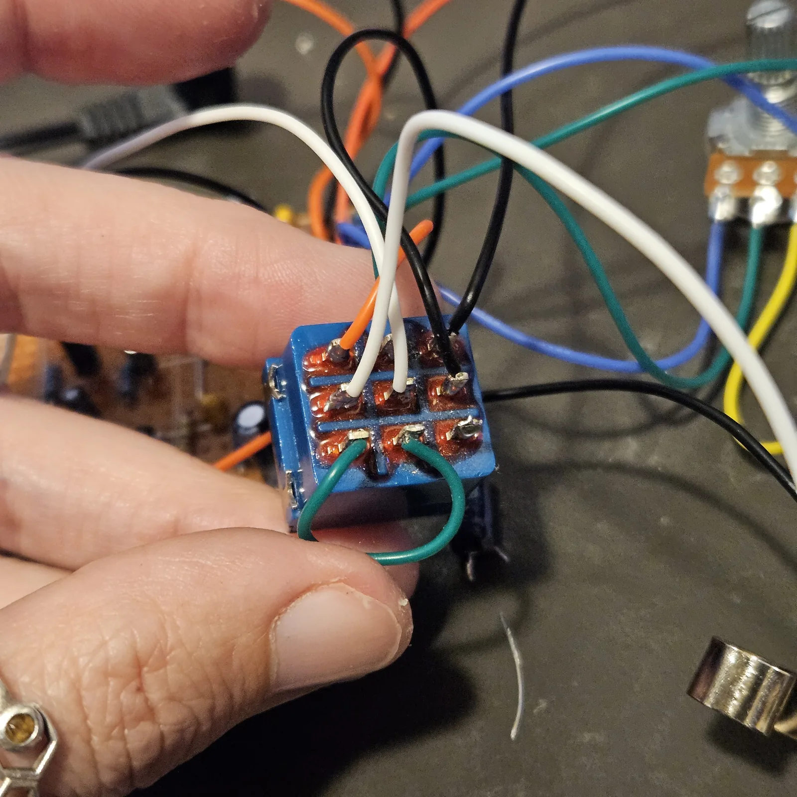
The board's output is whatever is last before the output jack. On a pedal with a volume knob that is the volume pot's wiper, not a pad on the board.
The LED's long leg goes to the supply through its resistor. Some boards have the resistor on the copper and a pad for the long leg; on the others, solder the resistor to the long leg and run it to the board's positive supply pad, after the power switch if the build has one.
Both jack sleeves go to the board's ground, and stay there. The footswitch never touches them.
3 Check it before the box is closed
With the power off and nothing plugged in, set the meter to beep.
| Probes on | Bypassed | Effect on |
|---|---|---|
| Input jack tip and output jack tip | Beeps | Silent |
| Input jack tip and the board's input | Silent | Beeps |
| The LED's short leg and ground | Silent | Beeps |
If the first row is silent both ways, the jumper is missing or on the wrong lugs. If the LED lights when the sound is bypassed, column 3 is wired the other way up from the first two: move the LED's wire to column 3's other end lug.
How it works, in one breath
Three switches share one button. In one position each middle lug meets its top lug: the input jack feeds the board, the board feeds the output jack, and ground reaches the LED's short leg, so it lights. In the other position each middle lug meets its bottom lug: the two jacks meet each other through the jumper, the board's input and output are both left open, and the LED loses its ground and goes dark.
Guides that use it
- Beetleworth is laid out for one: its IN and LED- pads go to the footswitch, and its page names every wire
- The other pedal layouts have no footswitch in their layout files. This wiring goes around any of them: the board's input pad, its output, and its ground
True bypass on a 3PDT is common practice among pedal builders and nobody's invention that I know of. The diagram and the words are mine, and so is anything wrong with them.