Beetle Compressor
A one-chip compressor · By Onion Madder · Mess O' Pedals
A compressor evens out how loud you play: a soft pick comes up, a hard strum is held down, and a note that fades away is pulled back up for longer. One NE571 does it, with the hook-up straight from its datasheet, on an 11 by 14 board. There is one knob, volume; how hard it squeezes is set by the chip.
It started as the Paper Beetle, and on paper it gets loud and crunchy and gives a nice big gnarly sound. This is the same circuit for a box: every part has the same name on both boards, and the one difference is the power LED, which sits on the paper but hangs off this board on wires, with its resistor still on the copper.
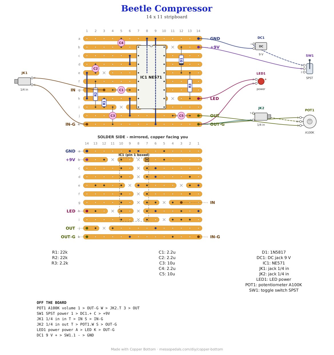
What you'll need
tap to expand / collapse
Nine parts on the board plus the chip and five links, and six off it.
- 1× NE571 compander, DIP-16 (IC1) - spot it: sixteen legs, NE571 printed on top, a notch or a dot at the pin 1 end. An NE570 or SA571 has the same pins. Only the left-hand half is used; on the right, only pin 13, the supply, is wired. It solders straight to the board
- 2× 22K resistor (R1, R2) - spot it: bands red-red-orange. They set where the output sits. R1 stands up on strips h and i; R2 lies from strip f down to strip i
- 1× 2.2K resistor (R3) - spot it: bands red-red-red. It feeds the power LED, which is off the board
- 3× 2.2 µF electrolytic (C1, C2, C4) - spot it: a small can with a stripe down one side; the stripe leg is the negative one. C4 smooths the chip's level detector, stripe up on strip a. C2 feeds the output back to the detector, stripe up on strip d. C1 takes the input in, lying along strip g with its stripe to the left, toward IN
- 2× 10 µF electrolytic (C3, C5) - spot it: the same kind of can, a little bigger. C3 steadies the DC feedback, stripe down on strip k. C5 is the output cap, lying along strip j with its stripe to the right, toward OUT
- 1× 1N5817 Schottky (D1) - spot it: fat black body, a gray band at one end. Reverse-polarity protection on the supply; it stands between strips b and e, band down on strip e, the chip's supply strip
- 5× wire links - offcuts of component leg. Two of them, J5 and J6, run under the chip's body, so they go in before the chip does
Off the board
- 1× A100K log pot - volume. Lug 3 to OUT, lug 1 to OUT-G, wiper to the output jack tip
- 2× 1/4 inch jacks - in on the left, out on the right. Input tip to IN, sleeve to IN-G; output tip to the volume wiper, sleeve to OUT-G
- 1× LED for power - long leg to LED, short leg to OUT-G. R3 on the board sets its current
- 1× DC jack, 9 V center negative
- An SPST toggle for power, in the positive supply lead between the DC jack and the board's +9V pad. Every build on this shelf gets one, and the drawing above shows it
The layout file is the guide
Like every layout on this shelf, the build document for this one is the file itself: ↓ Download Beetle_Compressor.json - import it into Copper Bottom and the editor gives you the board picture, the placement walkthrough, the electrical checks and a printable build sheet, all from the same file. No coordinates are written out on this page on purpose: the editor is the viewer, and a number typed twice is a number that can drift.
J5 and J6 run under the chip, so solder them before the chip goes in. J5 takes pin 4's ground up to strip a along the column between the pin rows, which is why pin 4's cut sits one hole further right than the others; J6 joins the two ground strips, a and k. The input comes in on the left and the output leaves on the right, the way the jacks go on my boxes.
Copper Bottom will say five things about pins 11, 12, 14, 15 and 16. They are the chip's second channel, which this build does not use, and the editor reports each one as the only thing on its strip. Leave them empty: the Paper Beetle has them empty and works. The NE571's datasheet does not promise that an unused channel may be left open, so the editor says so rather than stay quiet.
The netlist
My script wrote this from the design and the board was checked against it in Copper Bottom: every connection it names is on the board and nothing on the board is missing from it. The same script checks every net against the Paper Beetle's, so the two boards are one circuit. FB is the detector's input, fed from the output; OUTN is the chip's output and MID the middle of the DC loop. Pins 8 to 12 and 14 to 16 are left empty, which is why they are not listed.
The off-board wiring
Seven pads leave the board: the input and its ground, the output and its ground, the LED, and the supply.
| Pad | Goes to |
|---|---|
| IN | The input jack tip. A guitar, another pedal, a drum machine |
| IN-G | The input jack sleeve |
| OUT | Volume pot lug 3. The wiper goes to the output jack tip, and lug 1 to OUT-G |
| OUT-G | Volume pot lug 1, the output jack sleeve and the LED's short leg. Same net as GND |
| LED | The power LED's long leg |
| +9V / GND | The supply, through the power toggle. DC jack positive to the toggle and the toggle to +9V; negative to GND |
Before you play
Turn the volume down and switch it on: the LED should light. Then meter to ground, with nothing plugged in. These numbers are the datasheet and arithmetic, not off a built board.
| Meter | Expect |
|---|---|
| Pin 13 | The supply minus about 0.3 V, the drop across D1 |
| Pins 2, 3, 5 and 6 | About 1.8 V each, the chip's own reference, whatever the supply |
| Pin 7 | About 4.4 V, set by R1 and R2. Near 0 V or near the supply: look at R1, R2, C3 and strip i |
How it works, in one breath
Each half of an NE571 is a level detector, a gain cell and an op-amp. The datasheet's compressor puts the gain cell in the op-amp's feedback loop and points both the detector and the gain cell at the OUTPUT: C2 carries pin 7 back to pins 2 and 3. The louder the output gets, the more the gain cell lets through around the op-amp, and the less the op-amp amplifies, so the output only grows half as fast as the input in decibels: forty decibels of difference going in comes out as twenty. C4 on pin 1 is what the detector averages into, through the chip's own 10K, so the squeeze follows the playing over about twenty milliseconds rather than every wiggle of the wave.
The sound goes in through C1 and the chip's own 20K on pin 6. R1 and R2, with C3 from their middle to ground, are a feedback path for DC only: they hold the output at about 4.4 V, roughly half of what is left of 9 V after D1, so it can swing both ways, and C3 keeps them out of the sound. C5 takes the DC off the output, and the volume pot sets how much leaves.
Things to try
None of these have been tried on this board, and none on the paper one either.
- A slower squeeze. C4 at 10 µF smooths the detector about four and a half times longer, for a gentler swell. If low notes pump or flutter, 4.7 or 10 µF is the fix too
- After a fuzz. A compressor after a fuzz evens out its sputter on a fading note
- A buffer first. The input is the chip's own 20K, lower than most pedals, so a guitar plugged straight in may lose some top. Another pedal in front of it fixes that
The circuit is the Basic Compressor from onsemi's NE570 datasheet, the NE571's sibling with the same pins. The layout and the words are mine, and so is anything wrong with them.