Haunt Detector HD-C1
Ghost containment unit · By Onion Madder · Mess O' Pedals
A containment unit for whatever the other detectors find. The ghost is held on a tether, and the tether is the antenna's own signal: while the whip hears steady pickup, a ring of ten LEDs steps around the lid, clocked by that signal, and a green HELD lamp stays lit. Lose the signal for a second or two and the tether has snapped: the ring freezes, a red BREACH lamp comes on and a siren whoops until it comes back. The box is a metal pedal enclosure, which is a real Faraday cage, so the antenna is the only way in. The third model in the Haunt Detector series, after the HD-E1 and the HD-T1.
Before you start tap to expand / collapse
- The whip is an input, not a probe. It listens to the field around wiring from a distance. Never touch it to a live wire, an outlet or anything plugged in
- The BNC jack's center pin must never touch the box. If it does, the cage shields the antenna and the tether is dead. A BNC panel jack keeps the center insulated for you; only its shell bolts to the metal
- The box is grounded through the jack. The BNC shell's ground lug goes to board A's GND pad. That is what makes the box a cage rather than a second antenna
- The LMC6482, the 40106, the 4024 and the 4017 are CMOS and mind static. Touch something grounded before you handle them
What you'll need
tap to expand / collapse
Six chips and 46 small parts across the two boards, 29 links, and the panel parts. Every chip solders straight to its board.
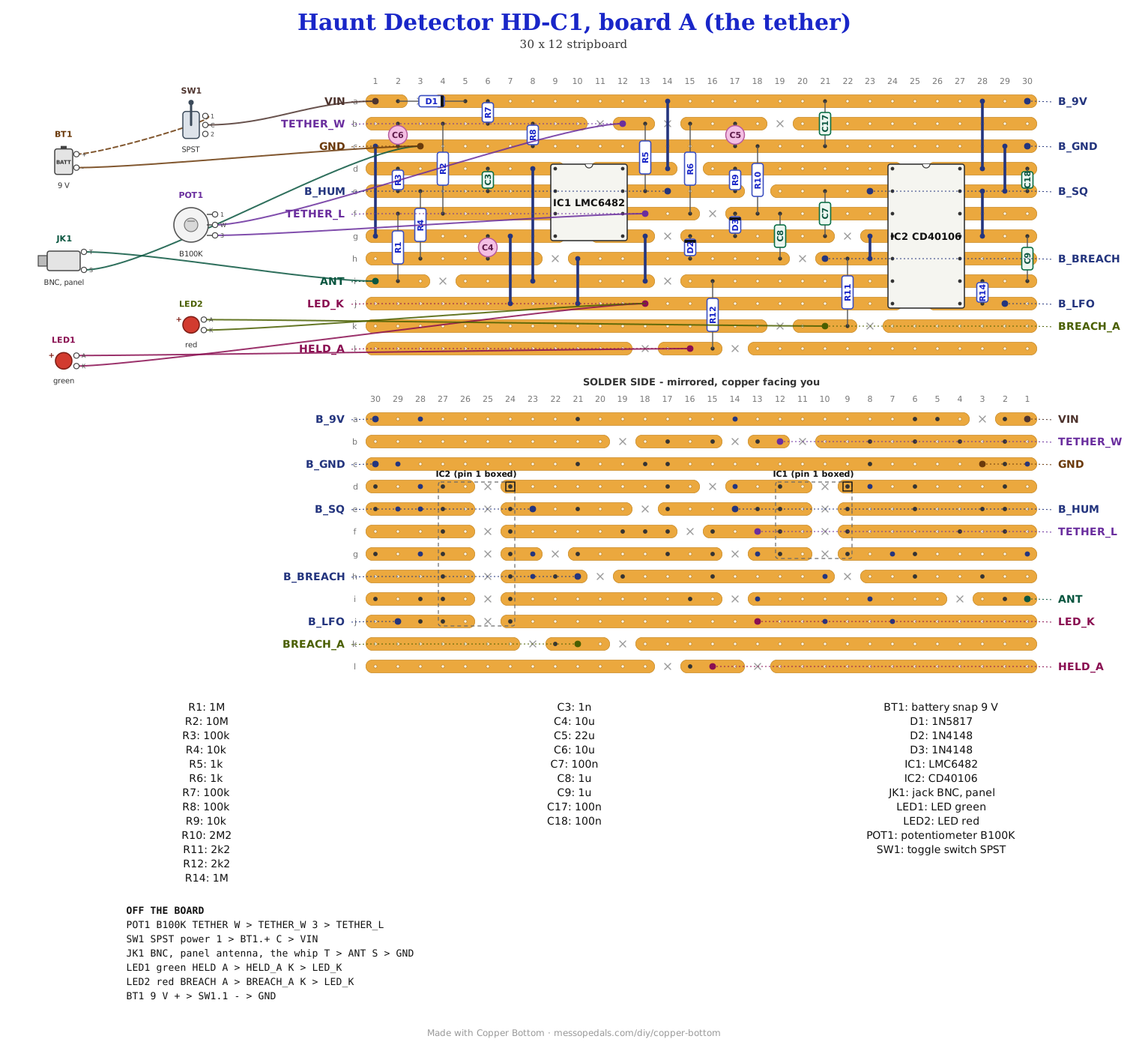
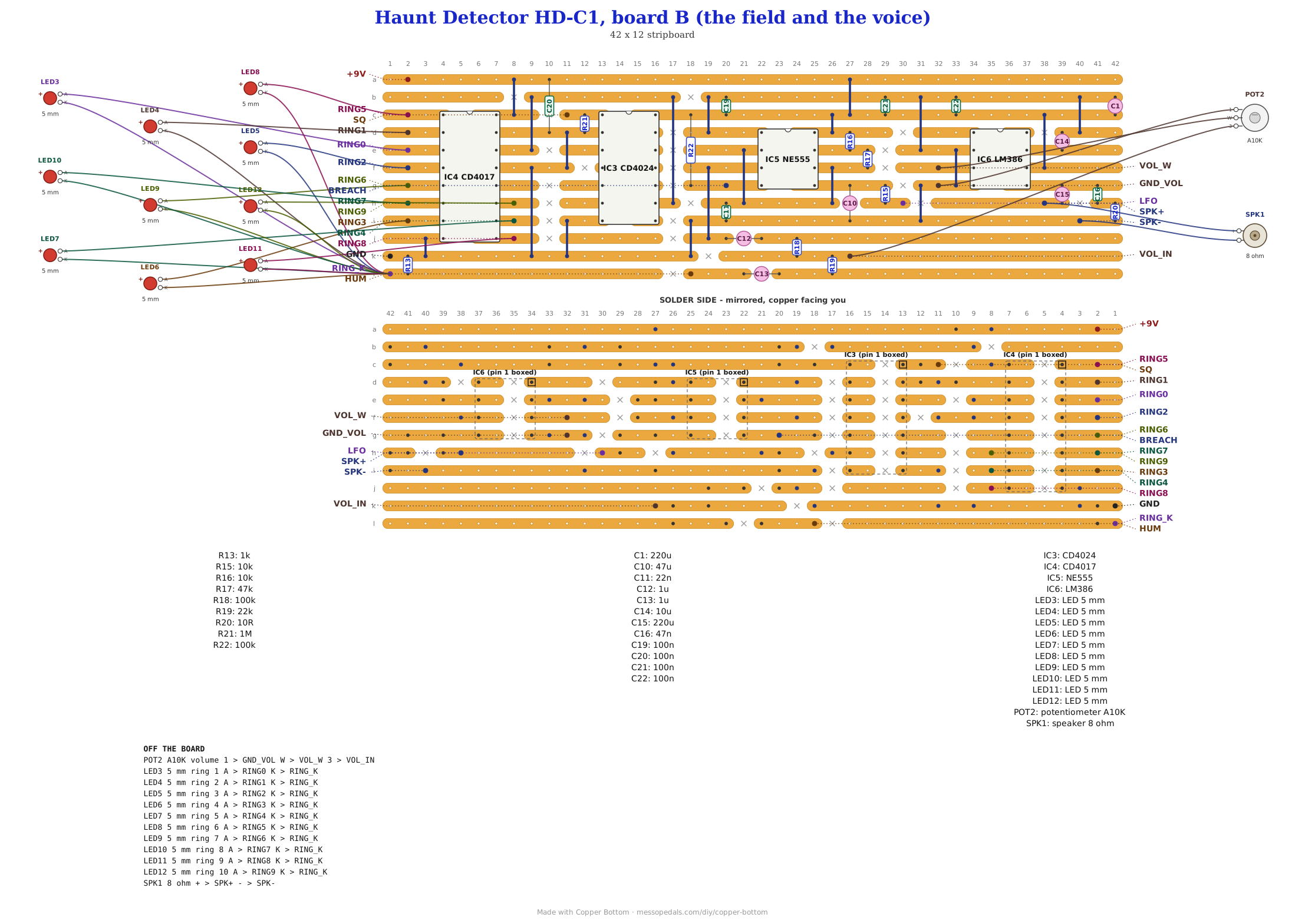
Board A takes IC1, IC2, R1 to R12, R14, C3 to C9, C17, C18 and D1 to D3. Board B takes IC3 to IC6, R13, R15 to R22, C1, C10 to C16 and C19 to C22.
- 1× LMC6482 dual op-amp, DIP-8 (IC1) - spot it: eight legs, LMC6482 on top. Its inputs draw almost nothing, which a 10M antenna input needs, and its outputs swing to both rails. A TL072 will not do here
- 1× CD40106 hex Schmitt inverter, DIP-14 (IC2) - spot it: fourteen legs, 40106 on top
- 1× CD4024 7-stage counter, DIP-14 (IC3) - spot it: fourteen legs, 4024 on top
- 1× CD4017 decade counter, DIP-16 (IC4) - spot it: sixteen legs, 4017 on top
- 1× NE555 timer, DIP-8 (IC5) and 1× LM386 speaker amp, DIP-8 (IC6) - spot it: the two eight-leg ones, by the name on top
- 5× 100K resistor (R3, R7, R8, R18, R22) - spot it: brown-black-yellow
- 4× 10K resistor (R4, R9, R15, R16) - spot it: brown-black-orange
- 3× 1M resistor (R1, R14, R21) - spot it: brown-black-green
- 3× 1K resistor (R5, R6, R13) - spot it: brown-black-red
- 2× 2.2K resistor (R11, R12) - spot it: red-red-red
- 1× each: 10M (R2, brown-black-blue), 2.2M (R10, red-red-green), 47K (R17, yellow-violet-orange), 22K (R19, red-red-orange) and 10 ohm (R20, brown-black-black)
- 7× 100nF ceramic (C7, C17 to C22) - spot it: printed 104
- 1× each ceramic: 47nF (C16, 473), 22nF (C11, 223) and 1nF (C3, 102)
- 2× 1 µF film (C8, C9) - spot it: a small box printed 105. C8 has to be film: it decides how long the box keeps holding after the signal goes, and an electrolytic that size leaks about as much as the pump puts in
- Electrolytics: 3× 10 µF (C4, C6, C14), 2× 1 µF (C12, C13), 2× 220 µF (C1, C15), and 1× each 22 µF (C5) and 47 µF (C10) - spot it: cans with a stripe down one side; the stripe leg is negative. All rated 16 V or more
- 1× 1N5817 Schottky (D1) - spot it: fat black body, gray band. It stops a battery put in backwards
- 2× 1N4148 (D2, D3) - spot it: small glass body, black band at one end. They are the pump
- 29× wire links, 10 on board A and 19 on board B - offcuts of component leg
Off the board
- 1× BNC panel jack, female, insulated center (JK1) - spot it: a round bayonet socket that bolts through a hole, with a solder cup on the center pin and a ground lug on the shell
- 1× BNC telescopic whip, sold for handheld scanners and radios - spot it: a collapsing aerial with a BNC plug on its foot. A whip pulled out of an old radio ends in a lug or a screw hole and will not fit a BNC
- 1× B100K linear pot (POT1) - TETHER
- 1× A10K log pot (POT2) - VOLUME
- 1× green LED (LED1, HELD) and 1× red LED (LED2, BREACH), 5 mm
- 10× 5 mm LEDs for the ring (LED3 to LED12), all one color - spot it: the long leg is the anode, the plus
- An SPST toggle for power (SW1), in the battery's plus lead before board A's VIN pad. Every build on this shelf gets one, and the drawing above shows it
- 1× 8 ohm speaker, half a watt, about 40 mm
- Power: at least two vape cells in series (7.4 V; three gives 11.1 V), or a 9 V battery
- Six lengths of hookup wire to join the boards: +9V, GND, SQ, BREACH, LFO and HUM
- A metal enclosure, the cage. The drill template is not drawn yet; a 1590BB is my guess at the size for the ring, two pots, two lamps, the jack, the speaker and the switch
The layout files are the guide
The circuit is split over two boards, so each half can be built and checked before the other one is started. Like every layout on this shelf, the build document is the file, one per board: ↓ Download Haunt_Detector_HD-C1_A.json and ↓ Download Haunt_Detector_HD-C1_B.json - import each into Copper Bottom and the editor gives you the board picture, the placement walkthrough, the electrical checks and a printable build sheet, all from the same file. No coordinates are written out on this page on purpose: the editor is the viewer, and a number typed twice is a number that can drift.
On board B, Copper Bottom gives two warnings, and both are meant: IC6's pins 1 and 8 connect to nothing, because the LM386 runs at a gain of 20 with its gain pins open. Board A comes back with no warnings. The chips go in last on both boards: solder everything else, do the meter checks below, then the chips.
Two boards, and either can be tried alone
Board A is the tether. With the battery, the switch, the jack, the TETHER pot and the two lamps wired on, it tells you on its own whether it hears anything: green for held, red for breach. Board B is the field and the voice, and it can be tried with nothing but +9V and GND: R22 holds its BREACH input high, so alone it wails, and R21 holds SQ low, so the ring sits still.
- Board A, then its meter checks, then its chips and the lamp test below
- Board B, wired to board A with B_9V to +9V, B_GND to GND, B_SQ to SQ, B_BREACH to BREACH, B_LFO to LFO and B_HUM to HUM
The netlists
My script wrote these from the design, one per board, and each board was checked against its own, by the script and in Copper Bottom: every connection a netlist names is on its board and nothing on the board is missing from it. The script also joins the two boards with their six wires and checks that the result is the whole circuit, net for net, and thirteen faults planted on purpose each made it fail. The NC lines are outputs and pins that are left unused: IC2's two spare gates, IC3's other counter outputs and its three empty pins, IC4's CARRY and the LM386's gain pins.
Board A
Board B
The off-board wiring
| Board | Pad | Goes to |
|---|---|---|
| A | VIN / GND | The battery, through the power toggle: battery plus to the toggle, the toggle to VIN; battery minus to GND |
| A | ANT | The BNC jack's center pin. Keep this wire short |
| A | GND | Also the BNC jack's shell lug, which grounds the box |
| A | TETHER_W / TETHER_L | The TETHER pot's wiper and lug 3. Lug 1 is left empty |
| A | HELD_A / BREACH_A / LED_K | The green HELD lamp's anode, the red BREACH lamp's anode, and both cathodes |
| B | RING0 to RING9 | The ten ring lamps' anodes, in order around the lid: ring lamp 1 on RING0 through ring lamp 10 on RING9 |
| B | RING_K | All ten ring cathodes, joined |
| B | VOL_IN / VOL_W / GND_VOL | VOLUME pot lug 3, wiper and lug 1 |
| B | SPK+ / SPK- | The speaker |
| A to B | B_9V, B_GND, B_SQ, B_BREACH, B_LFO, B_HUM | Board B's +9V, GND, SQ, BREACH, LFO and HUM, one wire each |
First power-up
- Board A, before its chips go in. Switch on and check the battery voltage, less about 0.3 V for D1, from the GND pad to the B_9V pad, and about half of that on C6's plus leg. That is VREF, the middle the front end works around
- Board A's chips, then the lamps. Solder IC1 and IC2 in, notch toward pin 1 as the file shows. Switch on with the whip off and TETHER all the way down: the red BREACH lamp should be lit, because there is nothing on the tether. Screw the whip on, pull it out, and turn TETHER up slowly until the green HELD lamp comes on and stays on
- Board B on its own. Before its chips go in, check for the supply at IC3 pin 14, IC4 pin 16, IC5 pin 8 and IC6 pin 6. Then solder the chips in and power it with only +9V and GND: it should wail, and the ring should sit still
- Both boards. Join the six wires. With the ghost held the ring steps about seven and a half times a second, a lap in about 1.3 seconds, and the speaker hums with whatever the whip hears. Walk the box away from the walls, or collapse the whip, and within a second or two the ring should freeze and the siren start
- If it holds everywhere, even with TETHER at zero, R2 (10M) is hearing too much: try 2.2M. If it never holds, even with TETHER up and the whip out next to a lamp cord, try 22M. How much a whip really hears in a house is the one thing the simulation could not say
How it works, in one breath
The metal box is a Faraday cage, so the only thing that reaches the circuit is what comes in on the whip, and indoors that is mostly the 60 Hz field around the house wiring. The whip feeds the first half of the LMC6482 through R1, held at the middle of the supply by the 10M R2, and that half gains it by 11. The second half gains it again by 2 to 102 on the TETHER pot, so TETHER sets how weak a signal still counts as held. One Schmitt inverter of the 40106 squares the result.
Every edge of that square wave pumps a little charge through C7, D2 and D3 into C8, and R10 drains it slowly. While the edges keep coming, C8 sits near 7 V and the ghost is held. When they stop, C8 runs down, and a second or two later a second inverter flips BREACH high and a third drops HELD. A front end that is stuck high or stuck low makes no edges at all, so a dead whip reads as a breach, never as a false hold.
On board B the same square wave clocks a 4024, which divides it by eight, and that clocks a 4017, which lights the ring one lamp at a time, so the ring only turns while the tether holds. The 555 is the siren, about 540 to 820 Hz, swung up and down a little over once a second by the fourth inverter on board A, and its reset pin listens to BREACH, so it only sounds on a breach. The siren and the whip's own hum meet at the VOLUME pot, and the LM386 plays them.
Things to try
None of these have been tried, because none of this has.
- A faster or slower ring. The ring is clocked from the 4024's pin 9, divide by eight. Its pin 11 divides by four, twice as fast, and pin 6 by sixteen, half as fast. That is a rewire of link J7 on board B, not a drop-in
- A longer grip. C8 bigger holds the ghost longer after the signal goes; R10 bigger does the same
- A different tether. A long wire strung across the room in place of the whip, or a coil of wire
The idea and the tether are mine. The diode pump as a missing-pulse detector, the 4017 ring and the 555 siren are standard parts of everyone's kit. The circuit and the layout were drawn for me, and anything wrong with them is mine to fix.