Haunt Detector HD-E1
EMF and E-field ghost detector · By Onion Madder · Mess O' Pedals
A handheld ghost detector for a 1590DD. Point it at something and a row of ten LEDs climbs and a voice rises in pitch. It has two noses: in EMF mode a pickup coil hears the magnetic hum around mains wiring, wall warts and anything with a transformer in it, and in E-field mode an antenna feels static, so a hand or a rubbed balloon near the tip sets it off. That is all it detects. What you tell people it detects is up to you.
What you'll need
tap to expand / collapse
Four chips, a transistor, a trimmer and 38 small parts across the two boards, 23 links, and a box full of things off them. Every chip solders straight to its board.
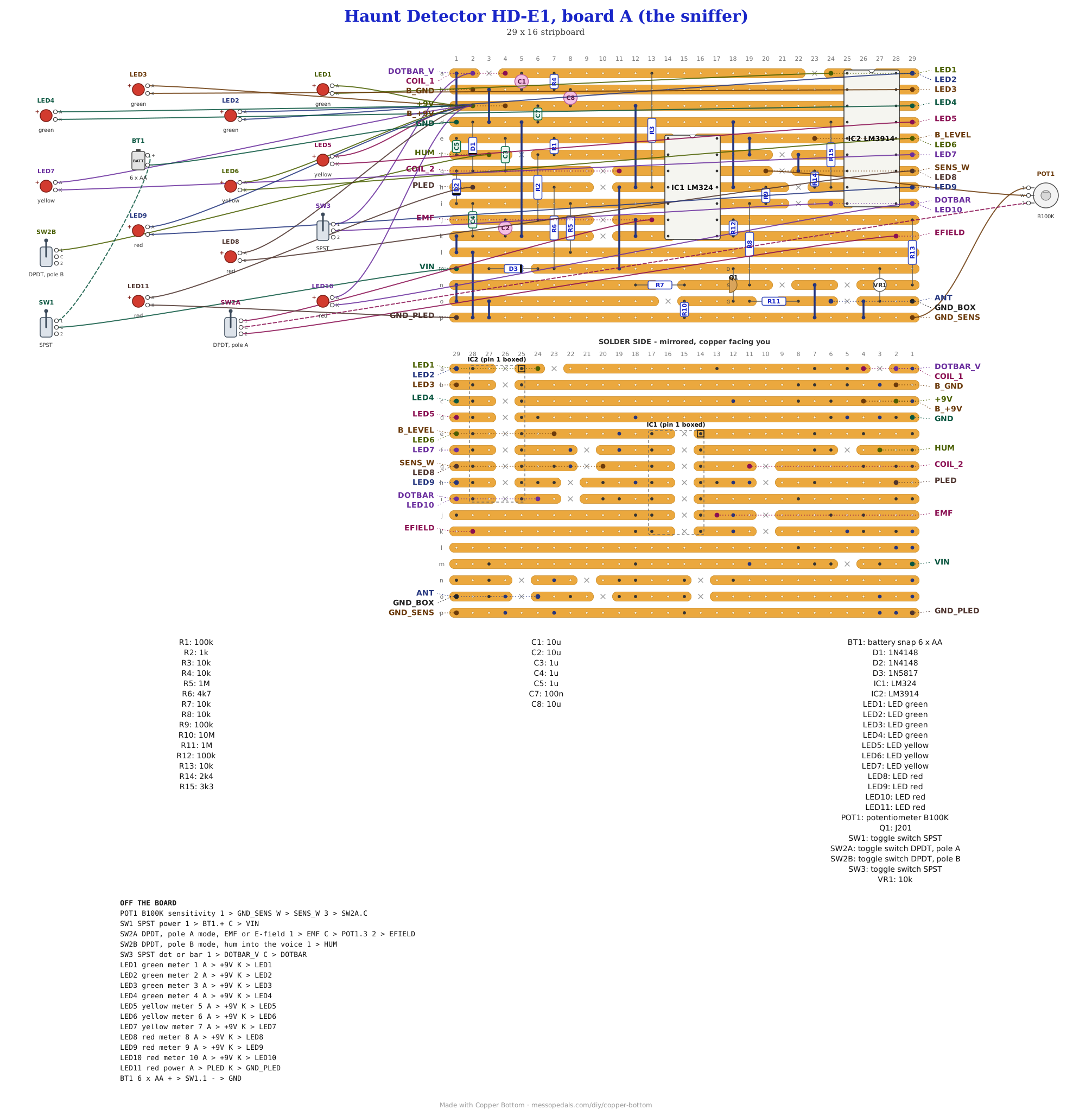
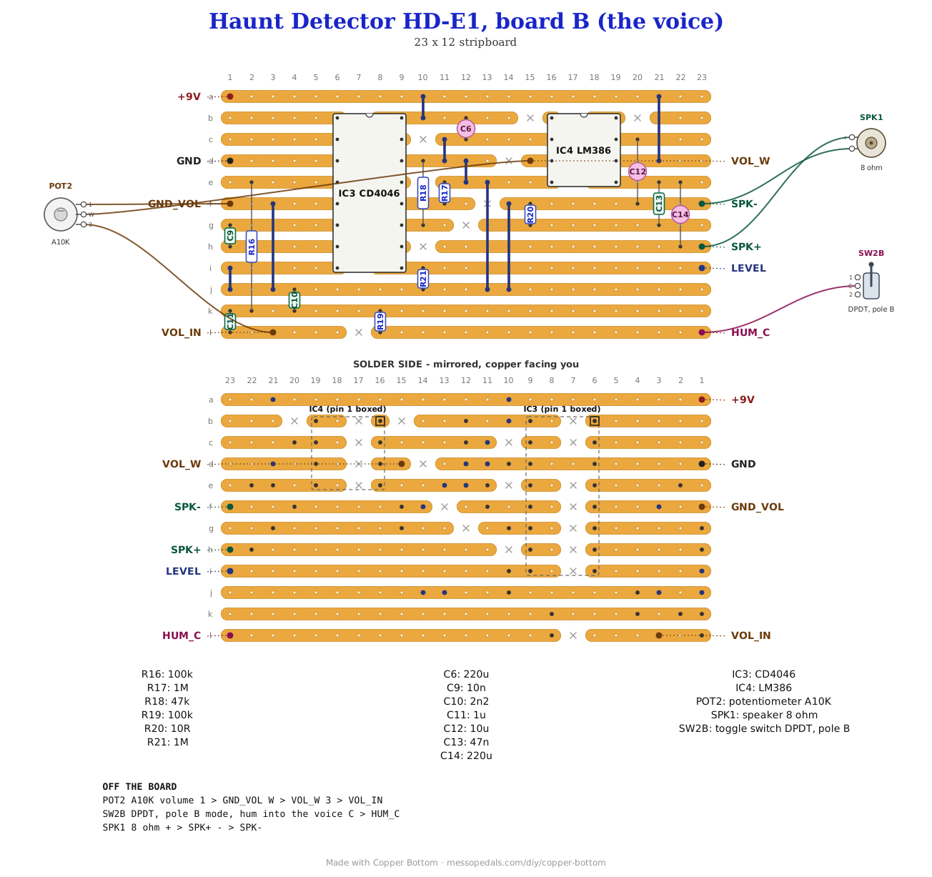
Board A takes IC1, IC2, Q1, VR1, R1 to R15, C1 to C5, C7, C8 and D1 to D3. Board B takes IC3, IC4, R16 to R21, C6 and C9 to C14.
- 1× LM324 quad op-amp, DIP-14 (IC1) - spot it: fourteen legs, LM324 on top. All four of its amps are used: two for the coil, one for the antenna, one for the meter
- 1× LM3914 bargraph driver, DIP-18 (IC2) - spot it: the long eighteen-leg one. Not an LM3915 or LM3916: those step in decibels and VU and will read differently
- 1× CD4046 PLL, DIP-16 (IC3) - spot it: sixteen legs, CD4046 or HEF4046 on top. Only its VCO is used
- 1× LM386 speaker amp, DIP-8 (IC4) - spot it: the little eight-leg one
- 1× J201 N-channel JFET (Q1) - spot it: a black TO-92 like a small transistor, J201 printed on the flat. Check your part's datasheet for which leg is which before it goes in: board A's file has drain on strip m, source on n and gate on o
- 1× 10K trimmer (VR1, ZERO) - spot it: a small square pot with a screw slot, marked 103
- 5× 100K resistor (R1, R9, R12, R16, R19) - spot it: brown-black-yellow
- 5× 10K resistor (R3, R4, R7, R8, R13) - spot it: brown-black-orange
- 4× 1M resistor (R5, R11, R17, R21) - spot it: brown-black-green
- 1× each: 10M (R10, brown-black-blue), 47K (R18, yellow-violet-orange), 4.7K (R6, yellow-violet-red), 3.3K (R15, orange-orange-red), 2.4K (R14, red-yellow-red), 1K (R2, brown-black-red) and 10 ohm (R20, brown-black-black)
- 4× 1 µF ceramic or film (C3, C4, C5, C11) - spot it: printed 105
- 4× 10 µF electrolytic (C1, C2, C8, C12) and 2× 220 µF electrolytic (C6, C14) - spot it: cans with a stripe down one side; the stripe leg is negative
- 1× each ceramic: 100nF (C7, printed 104), 47nF (C13, 473) and 2.2nF (C10, 222)
- 1× 10nF film or C0G (C9, printed 103) - the VCO's timing cap. A cheap ceramic drifts with temperature, so the pitch would too
- 2× 1N4148 (D1, D2) - spot it: small glass body, black band at one end
- 1× 1N5817 Schottky (D3) - spot it: fat black body, gray band. It stops a battery pack put in backwards
- 23× wire links, 15 on board A and 8 on board B - offcuts of component leg
Off the board
- 1× 100mH axial choke - the pickup coil. On a twisted pair to COIL_1 and COIL_2
- 1× telescoping antenna and an insulating grommet for it, to ANT
- 1× B100K linear pot - SENS
- 1× A10K log pot - VOLUME
- 1× DPDT toggle - MODE, EMF or E-field
- 1× SPST toggle - DOT/BAR
- An SPST toggle for power, in the battery's plus lead before the board's VIN pad. Every build on this shelf gets one, and the drawing above shows it
- 10× 3 mm LEDs for the meter, four green, three yellow, three red, and a scrap of stripboard 30 holes by 2 strips to mount them on
- 1× LED for the power light, red in the design
- 1× 8 ohm speaker, half a watt, about 40 mm
- 1× 6 × AA battery holder - six cells make 9 V
- Three lengths of hookup wire to join the boards: +9V, GND and LEVEL
- 1× Hammond 1590DD and a ground lug for it
The layout files are the guide
The circuit is split over two boards, so each half can be built and heard working before the other one is started. Like every layout on this shelf, the build document is the file, one per board: ↓ Download Haunt_Detector_HD-E1_A.json and ↓ Download Haunt_Detector_HD-E1_B.json - import each into Copper Bottom and the editor gives you the board picture, the placement walkthrough, the electrical checks and a printable build sheet, all from the same file. No coordinates are written out on this page on purpose: the editor is the viewer, and a number typed twice is a number that can drift.
On board A, three parts lie along a strip over a cut: D3 on strip m, R7 on strip n and R11 on strip o, so each one's two legs are on different copper even though they share a strip. On board B, strip a is +9 V and strip j is ground. The chips go in last on both boards: solder everything else, do the meter checks below, then the chips.
Build board A first
Board A is the half that senses, and it works on its own: with the LED board, the battery and its own panel parts wired on, the bargraph should climb when the coil or the antenna picks something up. Board B is the half that sings, and it can be tried on its own too.
- Board A. Build it, the LED board, and everything in the off-board table below that lands on board A. Do its first power-up, then point the coil at a wall wart. Between B_LEVEL and ground a meter should read from near 0 up to about 3 V as the bargraph climbs
- Board B, alone. Run two wires from board A, B_+9V to board B's +9V and B_GND to its GND, and leave LEVEL unwired. R21 holds the VCO's input low, so the speaker should give the bottom note of its range
- Then the third wire, B_LEVEL to board B's LEVEL, and the voice should rise as the bargraph does
R21 is the one part that was not in the circuit before it was split. Without it, board B tested alone would leave the 4046's VCO input hanging on a wire that is not there yet. Against the op-amp that drives LEVEL, a 1M to ground is no load at all.
The LED board
The meter's ten LEDs sit on their own scrap of stripboard, 30 holes long and 2 strips tall, so they can line up in a slot in the lid. Strip a is the shared anode strip; strip b carries each cathode on its own island.
- Cut strip b at holes 3, 6, 9, 12, 15, 18, 21, 24 and 27. That leaves ten islands of two or three holes
- LED1 to LED10 go in every third hole, starting at hole 1: long leg (anode) on strip a, short leg (cathode) on strip b. Four green, three yellow, three red, from LED1
- From the hole beside each cathode, a wire to its pad on board A, LED1 to LED10
- One wire from strip a, hole 30, to board A's +9V pad
The netlists
My script wrote these from the design, one per board, and each board was checked against its own, by the script and in Copper Bottom: every connection a netlist names is on its board and nothing on the board is missing from it. The script also joins the two boards with their three wires and checks that the result is the whole circuit, net for net, with R21 the only addition. On board B the four other NC lines are the CD4046's phase comparator and demodulator outputs, which are not used; NC_15 is its zener and NC_G1 and NC_G8 are the LM386's gain pins, left open for a gain of 20.
Board A
Board B
The off-board wiring
| Board | Pad | Goes to |
|---|---|---|
| A | VIN / GND | The battery, through the power toggle: battery plus to the toggle, the toggle to VIN; battery minus to GND |
| A | GND_BOX | The ground lug on the enclosure |
| A | PLED / GND_PLED | The power LED, anode and cathode |
| A | COIL_1 / COIL_2 | The pickup coil, on a twisted pair |
| A | ANT | The antenna, through its grommet. It must never touch the box |
| A | EMF / EFIELD | MODE switch, pole A, the EMF and E-field throws. Pole A's common goes to lug 3 of the SENS pot, a wire that never touches the board |
| A and B | HUM / HUM_C | MODE switch, pole B: its EMF throw to HUM on board A, its common to HUM_C on board B. The E-field throw is left empty |
| A | SENS_W / GND_SENS | SENS pot wiper and lug 1 |
| B | VOL_IN / VOL_W / GND_VOL | VOLUME pot lug 3, wiper and lug 1 |
| A | DOTBAR / DOTBAR_V | The two lugs of the DOT/BAR toggle. Closed is a bar, open is a single dot |
| A | +9V | The LED board's anode strip |
| A | LED1 to LED10 | The LED board, one cathode each |
| B | SPK+ / SPK- | The speaker |
| A to B | B_+9V, B_GND, B_LEVEL | Board B's +9V, GND and LEVEL, one wire each |
First power-up
- Board A, before its chips go in. Put the batteries in, switch on, and check for 9 V from ground (the GND pad) to the two holes where the chips' supply pins will go: IC1 pin 4 and IC2 pin 3. The power LED should already be lit
- Switch off, solder IC1 and IC2 in, notch toward pin 1 as the file shows, and switch on. In EMF mode LED1 may glow with nothing near: that is ordinary mains hum, and it is what the coil is there to hear
- Switch to E-FIELD with nobody near the antenna and turn the ZERO trimmer until LED1 just goes dark. Then wave a hand, or a rubbed balloon, near the tip
- Board B, before its chips go in. With its +9V and GND wired from board A, check for 9 V between strip a and strip j, and at IC3 pin 16 and IC4 pin 6. Then switch off and solder them in
- The coil and the antenna have to sit outside the aluminum, or behind a plastic nose: a metal box is a shield, and inside it neither one hears anything
How it works, in one breath
In EMF mode the pickup coil is the ear. It hangs between half the supply, which R3, R4 and C1 make, and the plus input of the first amp in IC1, which lifts its hum about a hundred times. C3, D1 and D2 turn that into a DC level on C4, which R5 lets fall back slowly, and the second amp copies it out as EMF_LEVEL. In E-field mode Q1 is the ear: its gate hangs on 10M, so the antenna can push it around, and the third amp takes Q1's output, subtracts whatever the ZERO trimmer is set to and gains the difference by ten.
MODE's first pole picks one of the two onto the SENS pot, and the fourth amp copies the wiper out as LEVEL. LEVEL drives two things. The LM3914 lights its ten LEDs in ten equal steps from 0 to about 3 V, a full scale R14 and R15 set. And the CD4046's VCO turns it into pitch, so the voice climbs as the meter does. R16 and C10 round the VCO's square wave off, MODE's second pole mixes in the coil's own hum through R19 in EMF mode, and the LM386 plays the lot through the speaker. LEVEL is the one signal that crosses from board A to board B, which is why the circuit splits there.
Things to try
None of these have been tried, because none of this has.
- A wall wart or a fridge in EMF mode. Transformers leak the most
- A bigger coil. More turns hear further; an old relay or transformer winding works
- Pitch range. C9 smaller goes higher, bigger goes lower; R17 sets where the sweep starts and R18 how far it goes
A coil into an op-amp for magnetic fields, a JFET on a high-value gate resistor for electric ones, and an LM3914 to show the result are the standard ghost-meter recipe and belong to everyone who has built one. This combination and the layout were drawn for me, and anything wrong with them is mine to fix.