Haunt Detector HD-T1
Magic-eye ghost detector · By Onion Madder · Mess O' Pedals
A ghost detector with two magic-eye tubes standing up through the lid of a 1590DD. The left eye watches for cold spots through a thermistor, the right eye watches for shadows through a light sensor, and a speaker throbs when the microphone picks up rumble too low to hear. It only answers change: a still room reads calm, and the green bars grow when something moves, then settle back. The second model in the Haunt Detector series, after the HD-E1.
Before you start: this one has 250 volts in it tap to expand / collapse
- The tubes run on about 250 V DC from a bought high-voltage module. That is enough to hurt. None of it touches either stripboard: it lives on the module, the two tube sockets and the wires between them
- The module's output stays charged after you switch off. The two 470K bleeder resistors drain it, but before you touch anything on the high-voltage side, put a meter across the module's output and wait until it reads under 30 V
- Insulate every high-voltage joint with heat-shrink, keep those wires away from the lid and the pots, and use wire rated for the voltage
- The pack is lithium. Charge it only with a charger made for a 3-cell lithium pack, which stops at 12.6 V. A plain 12 V adapter is not a charger. Never short the pack's leads
- Set both modules with a meter before the tubes are wired to them: the heater module to 6.3 V, the high-voltage module to about 250 V
What you'll need
tap to expand / collapse
Four chips, a regulator, two trimmers and 65 small parts across the two boards, 26 links, and a box full of things off them. Every chip solders straight to its board.
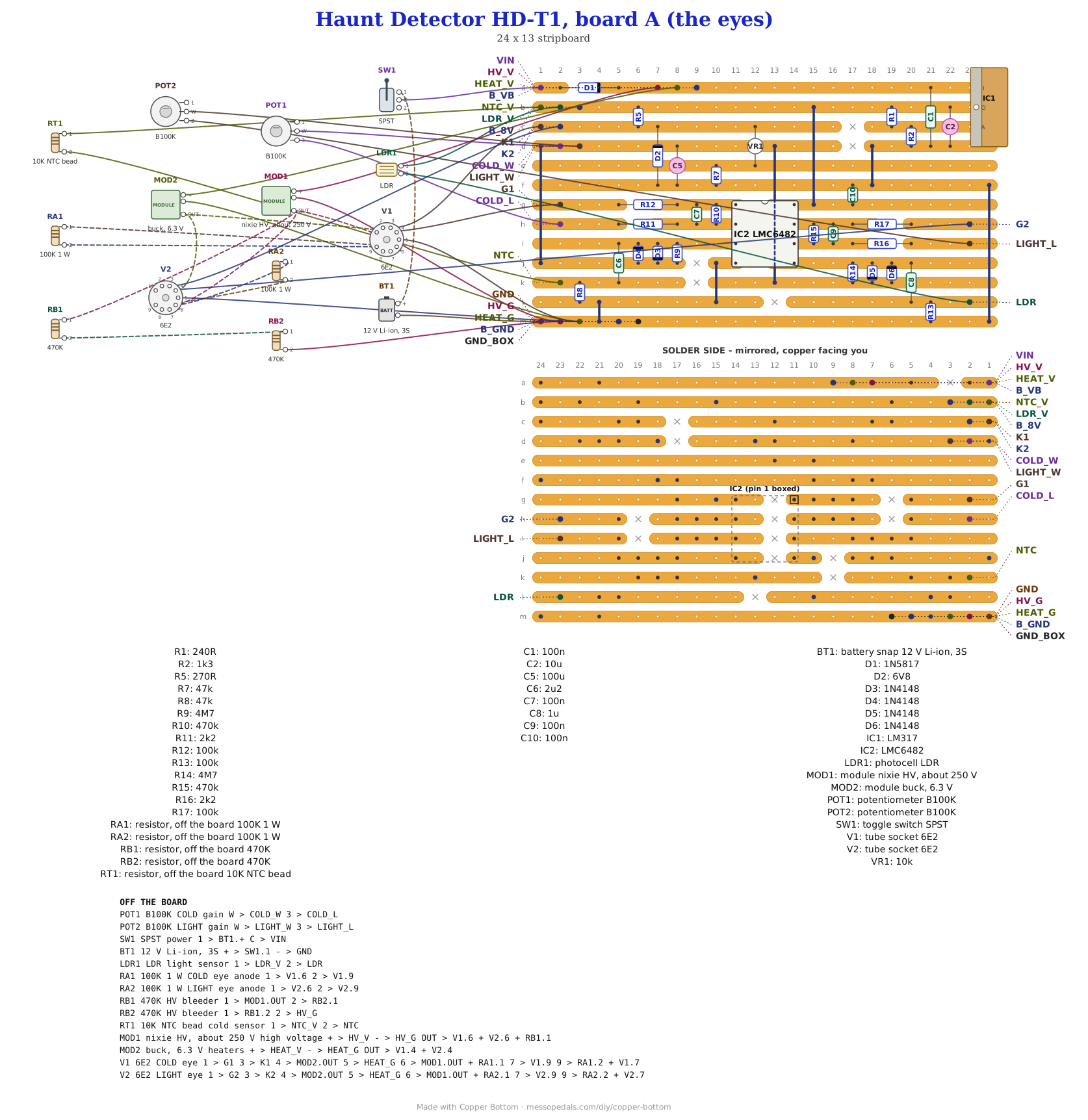
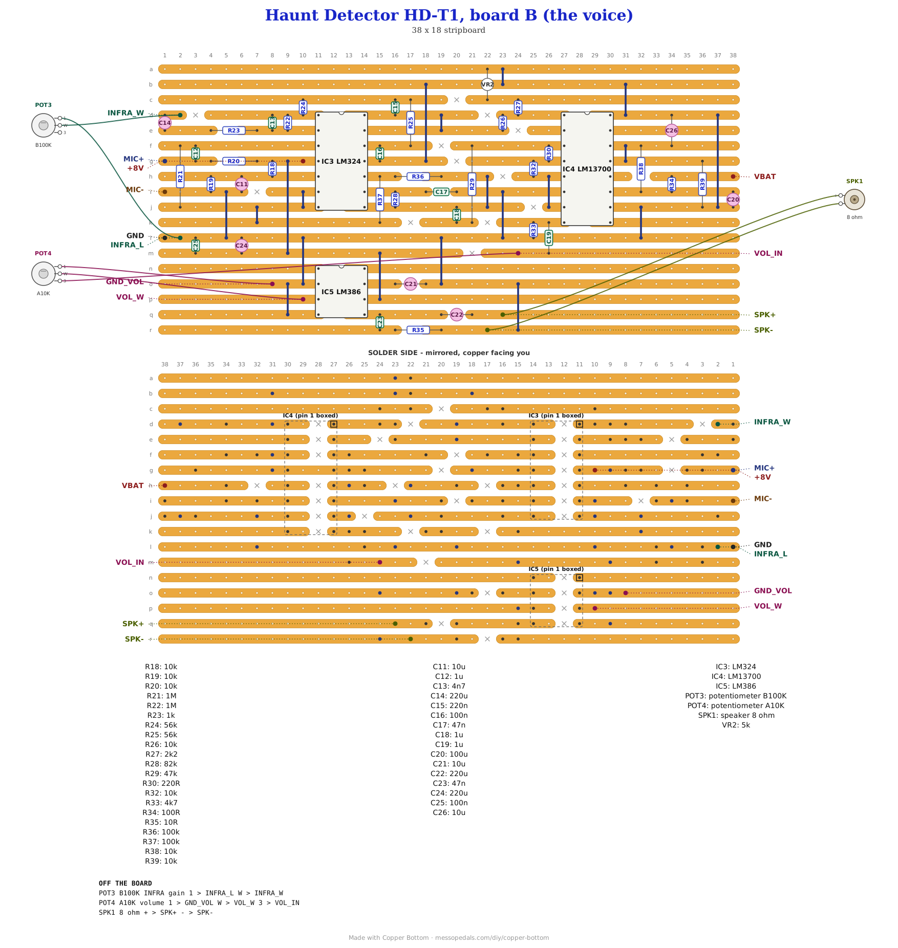
Board A takes IC1, IC2, VR1, R1, R2, R5, R7 to R17, C1, C2, C5 to C10 and D1 to D6. Board B takes IC3, IC4, IC5, VR2, R18 to R30, R32 to R39 and C11 to C26.
- 1× LM317 adjustable regulator, TO-220 (IC1) - spot it: a black block with a metal tab and three legs, LM317 printed on it. With the writing facing you its legs are adjust, output, input from the left; board A's file has input on strip a, output on b and adjust on c
- 1× LMC6482 dual op-amp, DIP-8 (IC2) - spot it: eight legs, LMC6482 on top. Its inputs draw almost nothing and its output swings to both rails, which the eye channels need. A TL072 will not do here
- 1× LM324 quad op-amp, DIP-14 (IC3) - spot it: fourteen legs, LM324 on top. All four amps are used
- 1× LM13700 dual OTA, DIP-16 (IC4) - spot it: sixteen legs, LM13700 on top. Only its first half carries signal
- 1× LM386 speaker amp, DIP-8 (IC5) - spot it: the little eight-leg one
- 1× 10K trimmer (VR1, REST) and 1× 5K trimmer (VR2, THRESH) - spot it: small square pots with a screw slot, marked 103 and 502
- 7× 10K resistor (R18, R19, R20, R26, R32, R38, R39) - spot it: brown-black-orange
- 5× 100K resistor (R12, R13, R17, R36, R37) - spot it: brown-black-yellow
- 3× 47K resistor (R7, R8, R29) - spot it: yellow-violet-orange
- 3× 2.2K resistor (R11, R16, R27) - spot it: red-red-red
- 2× each: 4.7M (R9, R14, yellow-violet-green), 470K (R10, R15, yellow-violet-yellow), 1M (R21, R22, brown-black-green) and 56K (R24, R25, green-blue-orange)
- 1× each: 82K (R28, gray-red-orange), 4.7K (R33, yellow-violet-red), 1.3K (R2, brown-orange-red), 1K (R23, brown-black-red), 270 ohm (R5, red-violet-brown), 240 ohm (R1, red-yellow-brown), 220 ohm (R30, red-red-brown), 100 ohm (R34, brown-black-brown) and 10 ohm (R35, brown-black-black)
- 5× 100nF ceramic (C1, C7, C9, C10, C25) - spot it: printed 104
- Film caps, each one a box: 2.2 µF (C6, 225), 3× 1 µF (C8, C12, C19, 105), 220nF (C15, 224), 100nF (C16, 104) and 47nF (C17, 473). C6 and C8 have to be film: they decide how long each eye holds a change, and a ceramic that big leaks and wanders
- 1× each ceramic: 1 µF (C18, 105), 47nF (C23, 473) and 4.7nF (C13, 472)
- Electrolytics: 4× 10 µF (C2, C11, C21, C26), 2× 100 µF (C5, C20) and 3× 220 µF (C14, C22, C24) - spot it: cans with a stripe down one side; the stripe leg is negative. All rated 16 V or more
- 1× 1N5817 Schottky (D1) - spot it: fat black body, gray band. It stops the pack plugged in backwards
- 1× 6.8 V zener, 1N4736A (D2) - spot it: small glass or black body, 4736 printed on it. It holds both tube cathodes at 6.8 V
- 4× 1N4148 (D3 to D6) - spot it: small glass body, black band at one end
- 26× wire links, 7 on board A and 19 on board B - offcuts of component leg
Off the board
- 2× 6E2 magic-eye tubes, the Chinese 6E2 - spot it: a nine-pin glass tube with a green fluorescent screen inside. Its bars grow from both ends of the screen at once. The Soviet 6E2P is a different tube, a sliding spot with a 0.58 A heater and other pins, and will not drop in
- 2× nine-pin (B9A, noval) chassis sockets, to stand the tubes up through the lid
- 2× 100K 1 W resistors (RA1, RA2), the anode resistors, one on each socket from pin 6 to pin 9. A jumper from pin 7 to pin 9 on each socket as well
- 2× 470K resistors (RB1, RB2), the bleeder, in series across the high-voltage module's output
- 1× nixie high-voltage module (MOD1) that runs from 12 V and can be set to about 250 V
- 1× buck module (MOD2) that can be set to 6.3 V and give 1 A, for the two heaters, 0.3 A each
- 1× 10K NTC bead thermistor, B 3950 (RT1) - the cold sensor. Mount it where the air can reach it, outside the box
- 1× LDR (LDR1) - the light sensor, also where it can see out
- 1× electret mic capsule, two legs - spot it: the leg joined to the metal case is minus
- 3× B100K linear pot - COLD, LIGHT and INFRA
- 1× A10K log pot - VOLUME
- An SPST toggle for power, in the pack's plus lead before board A's VIN pad. Every build on this shelf gets one, and the drawing above shows it
- 1× 8 ohm speaker, half a watt, about 40 mm
- 1× 12 V rechargeable lithium pack, three cells (11.1 V, 12.6 V full) with its own protection board, and a charger made for it. Mine is about 4 by 3 by 1 inches and fills one end of the box
- Three lengths of hookup wire to join the boards: VBAT, +8V and GND, and wire rated for 300 V or more for the high-voltage runs
- 1× Hammond 1590DD and a ground lug for it
The layout files are the guide
The circuit is split over two boards, so each half can be built and checked before the other one is started. Like every layout on this shelf, the build document is the file, one per board: ↓ Download Haunt_Detector_HD-T1_A.json and ↓ Download Haunt_Detector_HD-T1_B.json - import each into Copper Bottom and the editor gives you the board picture, the placement walkthrough, the electrical checks and a printable build sheet, all from the same file. No coordinates are written out on this page on purpose: the editor is the viewer, and a number typed twice is a number that can drift.
On board B, Copper Bottom gives three warnings, and all three are meant. The strip under IC4 at its pins 4 and 13 is left whole, because both pins sit on the OTA's own reference and that strip is how they meet. IC5's pins 1 and 8 connect to nothing, because the LM386 runs at a gain of 20 with its gain pins open. Board A comes back with no warnings. The chips go in last on both boards: solder everything else, do the meter checks below, then the chips.
Build board A first
Board A is the half with the eyes, and it works on its own: with the pack, the power switch, the sensors and the two pots wired on, the meter checks below tell you it is right before a tube or a module is anywhere near it. Board B is the half with the voice, and it can be tried on its own too, from board A's three wires.
- Board A, then its meter checks. Then set the two modules, then wire the tubes
- Board B, wired to board A with B_VB to VBAT, B_8V to +8V and B_GND to GND. It needs all three: the LM386 and the LM324 run on 8 V, the LM13700 on the pack
The LM13700 runs on the pack, through R34 and C20, rather than on 8 V, because it wants 10 V or more to bias properly. The pack sits between 10 and 12.6 V for its whole charge. Everything else runs on 8 V and not 9, because the LM317 needs about 2 V of headroom: at 9 V it would drop out as the pack ran down, and the eyes would start to flicker in time with the speaker.
The netlists
My script wrote these from the design, one per board, and each board was checked against its own, by the script and in Copper Bottom: every connection a netlist names is on its board and nothing on the board is missing from it. The script also joins the two boards with their three wires and checks that the result is the whole circuit, net for net. On board B the NC lines are the LM13700's unused pins (its first half's diode bias, and the outputs of its second half, which carries no signal) and the LM386's gain pins.
Board A
Board B
The off-board wiring
| Board | Pad | Goes to |
|---|---|---|
| A | VIN / GND | The pack, through the power toggle: pack plus to the toggle, the toggle to VIN; pack minus to GND |
| A | GND_BOX | The ground lug on the enclosure |
| A | HV_V / HV_G | The high-voltage module's input, plus and minus. The bleeder's bottom end joins HV_G too |
| A | HEAT_V / HEAT_G | The heater module's input, plus and minus. Pin 5 of both tube sockets joins HEAT_G too |
| Off board | - | The high-voltage module's output to pin 6 of both sockets and the top of the bleeder. The heater module's output to pin 4 of both sockets. On each socket the 100K 1 W from pin 6 to pin 9, and a jumper from pin 7 to pin 9. Pins 2 and 8 stay empty |
| A | K1 / G1 | The left tube, COLD: K1 to socket pin 3, the cathode; G1 to socket pin 1, the grid |
| A | K2 / G2 | The right tube, LIGHT: K2 to socket pin 3; G2 to socket pin 1 |
| A | NTC_V / NTC | The thermistor, one lead each |
| A | LDR_V / LDR | The LDR, one lead each |
| A | COLD_W / COLD_L | The COLD pot's wiper and lug 3. Lug 1 is left empty |
| A | LIGHT_W / LIGHT_L | The LIGHT pot's wiper and lug 3. Lug 1 is left empty |
| B | MIC+ / MIC- | The electret mic: MIC- to the leg joined to its case |
| B | INFRA_W / INFRA_L | The INFRA pot's wiper and lug 1. Lug 3 is left empty |
| B | VOL_IN / VOL_W / GND_VOL | VOLUME pot lug 3, wiper and lug 1 |
| B | SPK+ / SPK- | The speaker |
| A to B | B_VB, B_8V, B_GND | Board B's VBAT, +8V and GND, one wire each |
First power-up
- Board A, before IC2 goes in, and with no tubes or modules wired. Plug in the pack, switch on, and check for 8 V from ground (the GND pad) to the B_8V pad, and 6.8 V at K1 and K2. Then measure COLD_W and turn the REST trimmer: it should move between about 5.6 and 6.8 V
- The modules. Switch off, wire the two modules' inputs to their pads, switch on, and set each one with a meter on its output: the heater module to 6.3 V, the high-voltage module to about 250 V. Switch off and wait for the high-voltage side to drain under 30 V
- The tubes. Solder IC2 in, notch toward pin 1 as the file shows, wire both sockets, and switch on. The heaters glow first and the screens light after 20 or 30 seconds. The eye channels settle in 10 to 15 seconds at middle gain, and up to about 45 seconds with COLD turned all the way up
- REST: with both pots low, turn the trimmer until the bars just show on both screens. That is the calm reading. Then turn COLD and LIGHT up until a breath on the thermistor or a hand over the LDR moves them as far as you want
- Board B, before its chips go in. With its three wires from board A, check for 8 V at IC3 pin 4 and IC5 pin 6, and the pack's voltage, less a little, at IC4 pin 11. Then switch off and solder the chips in
- THRESH: with INFRA low and the room quiet, turn the trimmer until the tone just goes silent. Then turn INFRA up and tap the box, or shut a door in the next room
How it works, in one breath
A 6E2 shows its grid voltage as two green bars: the more negative the grid is against the cathode, the longer the bars. Both cathodes sit on a 6.8 V zener, so an op-amp running on 8 V can take each grid from level with its cathode down to about 6.8 V below it. The REST trimmer sets where each grid idles, just under the cathode, where the bars just show.
For COLD, the thermistor over R8 makes a voltage that falls as the air cools. C6 lets only the change through, onto a node R9 holds at the rest voltage, and the first half of the LMC6482 gains that change 5 to 215 times, set by the COLD pot. Colder pulls the grid negative and the bars grow; the 2.2 µF and the 4.7M let the eye forget a change in about ten seconds, so a slow drift in the room barely moves it. D3 and D4 let a big jump, like switching on, settle in moments instead of a minute. LIGHT is the same again with the LDR, C8 and the second half of the chip, and forgets in about five seconds.
The voice starts at the mic. The first amp of the LM324 gains it 11 to 1001 times on the INFRA pot, and a second amp is a filter that passes only what is below about 19 Hz. That rumble pushes a current into the LM13700, which passes a steady low tone from the LM324's third amp, a Schmitt oscillator near 116 Hz, only while the rumble pushes. So the tone throbs once per cycle of the rumble, and THRESH sets how hard it has to push. The LM386 plays it through the speaker. Whether a cheap electret hears below 20 Hz at all is the open question on this build, and the one the bench will answer.
Things to try
None of these have been tried, because none of this has.
- An ice cube near the thermistor, and a hand over the LDR, to find where COLD and LIGHT want to sit
- A slower eye. C6 bigger holds a cold spot longer; C8 bigger does the same for LIGHT
- A pitch for the throb. R28 smaller raises the tone, bigger lowers it
Magic eyes were how a radio showed you were tuned to the station, and using one as a meter is borrowed from that. The thermistor and LDR dividers, the op-amp gain stages and the LM13700 as a gate are standard parts of everyone's kit. This combination and the layout were drawn for me, and anything wrong with them is mine to fix.