Dragonfly VCO
A CD4046 phase-locked loop used as an oscillator, drawn in Copper Bottom and built · By Onion Madder · Mess O' Pedals
The Dead-Bug Dragonfly on copper. A CD4046 is a phase-locked loop - a chip built to make one signal follow another - and almost every synth build ignores the following half and uses it as a plain, very well-behaved voltage-controlled oscillator. This one keeps both. There is a pitch knob for playing it, and there is an input and a mode switch for letting the loop chase whatever you feed it.
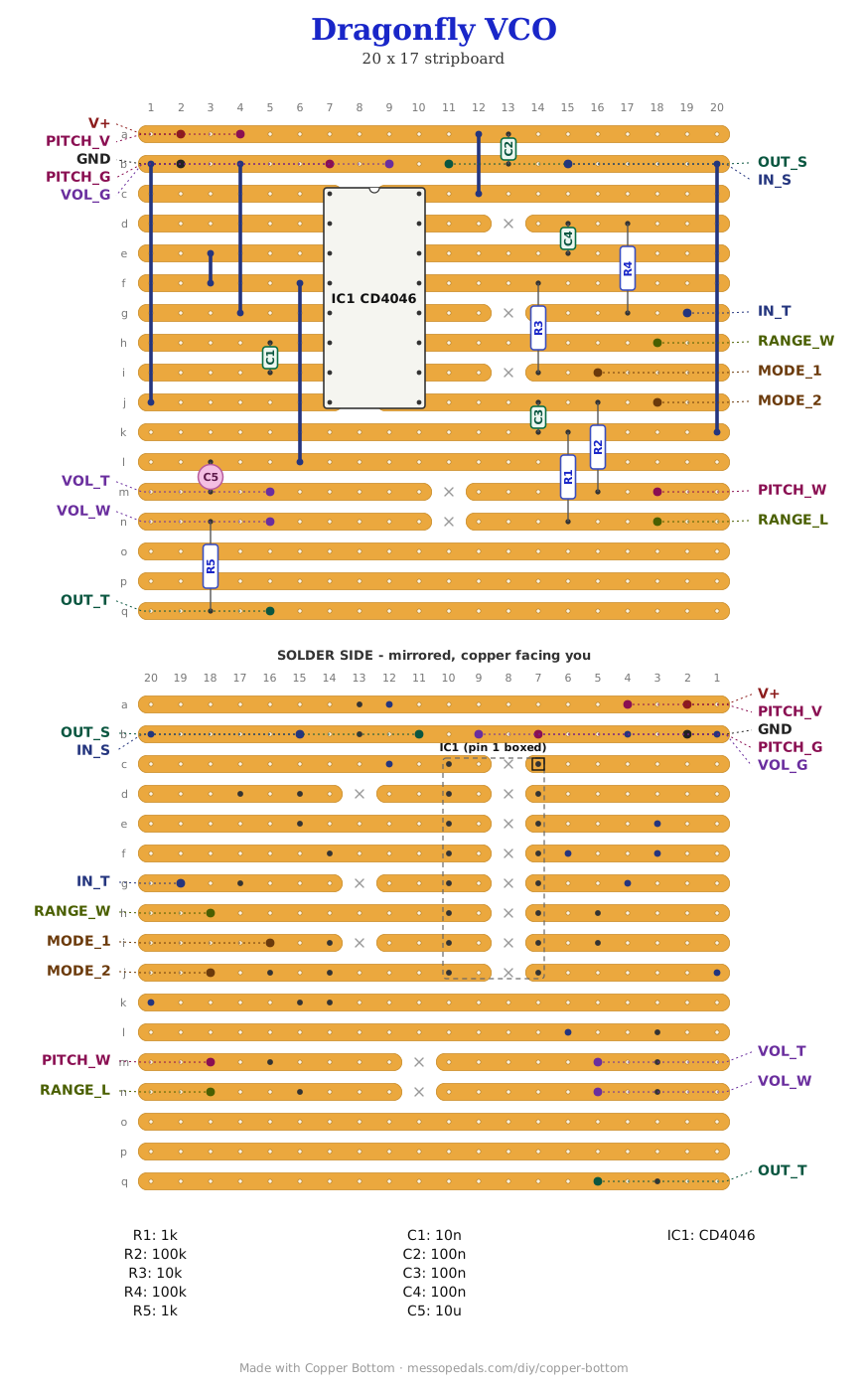

What you'll need
tap to expand / collapse
- 1× CD4046 phase-locked loop, 16-pin DIP - spot it: CD4046 printed on top, notch marks pin 1
- 1× 10n ceramic (printed 103) - the VCO's timing cap, and the thing that sets its range. Bigger means lower
- 3× 100n ceramic (104) - supply decoupling and two in the control path
- 1× 10 µF electrolytic - the output DC blocker
- 2× 1K (brown-black-red), 1× 10K (brown-black-orange), 2× 100K (brown-black-yellow)
- 1× stripboard, 9 strips × 14 holes or larger, and wire for four links
Off the board
- 3× 100K pots, off-board - pitch, range and volume. Spot it: B100K is the linear one
- 1× SPDT switch for the mode, and two jacks - one in, one out
- 1× 9V supply. A 4046 runs from 3V to 18V
- 1× 9V battery snap or a DC jack
- On my box, not in the file: a 100K pot in the supply leg as a starve, a toggle for power, a UV LED across strips 13 and 14 of the built board (the PITCH_W and RANGE_L strips), and a second toggle for the octave-drop bend described further down. Two 3.5 mm jacks in place of quarter-inch, which is what the drill template is cut for
- An SPST toggle for power, in the positive supply lead between the DC jack or battery and the board's supply pad. Not in the layout file - it is off the board, and every build on this shelf gets one
The layout file is the guide
Like the 555 theremin and the Opto Duet, the build document for this one is the file itself: ↓ Download Dragonfly_VCO.json - import it into Copper Bottom and the editor gives you the board picture, the placement walkthrough, the electrical checks and a printable build sheet, all from the same file. No coordinates are written out on this page on purpose: the editor is the viewer, and a number typed twice is a number that can drift.
The netlist
Quoted verbatim from the layout file. It was written from the board, so checking the board against it can only pass - what it is for is carrying the circuit somewhere else, and telling you what each strip is supposed to be doing while you stare at it.
The off-board wiring
Sixteen pads leave the board.
| Pad | Goes to |
|---|---|
| V+ / GND | The supply. PITCH_V and PITCH_G are the same two rails brought out again so the pitch pot has its own ends to sit across without a second wire back to the board |
| PITCH_V / PITCH_W / PITCH_G | The pitch pot, all three lugs - a divider this time, not a variable resistor, because pin 9 wants a control voltage rather than a resistance. Wiper to PITCH_W |
| RANGE_W / RANGE_L | The range pot, wiper and one lug. This one sets how far the pitch knob can sweep - the 4046 calls it R1 |
| MODE_1 / MODE_2 | The mode switch. MODE_2 is the VCO's control-voltage node; MODE_1 comes off the phase comparator. Join them and the chip starts trying to lock onto whatever is at the input instead of sitting where the knob put it |
| IN_T / IN_S | Input jack, tip and sleeve - what the loop chases in the second mode |
| VOL_T / VOL_W / VOL_G | Volume pot, all three lugs: a divider, so it can reach silence |
| OUT_T / OUT_S | Output jack, tip and sleeve |
Built, and heard
Built on the bench in September 2026, straight off the first drawing of this board - 17 strips by 20 holes, kept here as Dragonfly_VCO_v1.json - and it works. The 9 by 14 file above is the same circuit on less copper, every net checked against the built board, and I have built that one too, in October 2026: it sounds exactly like it is supposed to. I left the mode toggle and the power toggle off that board, so on it the mode switch and the input's chase are untried. The first board also sounds incredible - that is the word I used the moment it came up, and I am not taking it back. The 4046 tracks the way the dead-bug version promised it would, and with something on the input jack and the mode switch thrown it goes hunting the way the paragraph below says. Not boxed yet; the drill template further down is still a proposal.
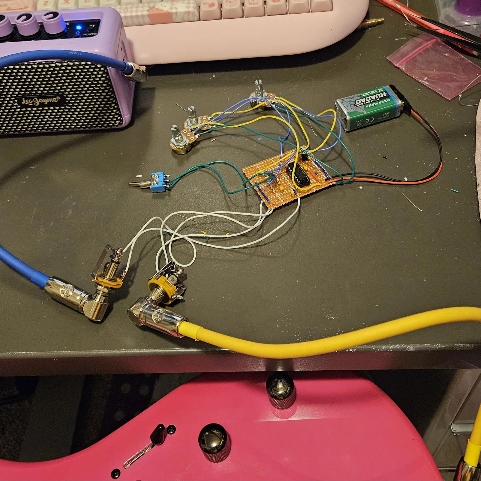
My box has more on it than the file does: a 100K starve pot in the supply leg, a power toggle, an LED, and a bend I found while poking at it - a toggle between the range pot's bare lug and pin 16, the lug the board does not use and the chip's supply pin. Throw it and the tone drops, about an octave. My reading of why, unmeasured: it puts the supply onto the range pot's track, so the pin-11 end is pulled up toward V+ and the current that sets the VCO's rate falls. Less current, lower pitch, and how far it falls depends on where the range knob sits.
The LED is a bend too, not an indicator. It is a UV LED across strips 13 and 14 of the built board - the pitch pot's wiper strip and the strip at the bottom of the range pot, just above its 1K floor - and it does two things at once: it flickers with the pitch knob, and it drops the tone as well, so the box never sits up in a thin whine. Same reading as the toggle: current from the pitch wiper through the LED follows the knob, which is the flicker, and what it dumps into the range pot's floor lifts that node and takes current away from the rate pin, which is the drop. It lights, so its anode must be on the pitch side, and it has no resistor in series - the pot track and the 1K floor are all that limits it. A pink LED in the same spot dropped it too far; a near-UV one needs more volts before it conducts, so it passes less current into that node and takes less off the pitch. None of this is in the layout file; the drill template further down is drawn for this box, so it has holes for all of it. On the smaller file above, those two strips are the ones carrying the PITCH_W and RANGE_L pads.
How it works, in one breath
The VCO half of a 4046 is one cap and two resistors. The cap between pins 6 and 7 sets the range, the resistor on pin 11 sets how wide the sweep is, and the voltage on pin 9 sets the pitch inside that. That is all a knob has to do here, and it is why this chip tracks so much more evenly than a 40106 does - it was designed to be steered.
The other half is a phase comparator: it looks at the VCO against whatever is on the signal input and puts out a voltage saying which is ahead. Feed that voltage back into pin 9 - which is what the mode switch does - and the oscillator stops obeying the knob and starts hunting for the input. On a bench that is a tracking oscillator. On a noisy input it is something much less obedient, which is the interesting setting.
Pin 15 is unconnected and should be. It is the chip's internal zener, unused in almost every build, and Copper Bottom will report it as an orphan every time you check this board. That one is expected. Pin 12 is left open too, which sets no floor on the lowest frequency the VCO will reach.
↓ Same box, DC and output on top (PDF)
The second sheet keeps every control and the CV input where this one has them and moves the DC jack and the output to the top wall, so those cables leave upward. Two ways to drill one box; pick one.
Drawn for the layout file's parts and nothing else: the three pots down the left, the mode toggle and the CV input on the right, the output and a DC jack along the bottom. My boxed build has more on its face - a supply starve, a power toggle, the DROP bend, an LED, and 3.5 mm jacks - and none of that is on this sheet; the parts list above says what those extras are.
Print at 100% / “Actual size”, never “Fit to page” - check the bar measures exactly 4″ before you touch a drill. The face is 66 by 121 mm but only 42 mm of it is drillable once the lid lip is clear.
Nobody has drilled this one yet. Where the holes sit is the house format applied to the parts; offer the sheet up to the box and check it against your own parts before you make a hole.
Circuit after the classic 4046 VCO, the same chip behind the Dead-Bug Dragonfly. Layout drawn by Onion Madder in Copper Bottom.