Weird Sound Generator
Ray Wilson's MFOS WSG · Andrew Sharp's stripboard layout · Traced by Onion Madder · Mess O' Pedals
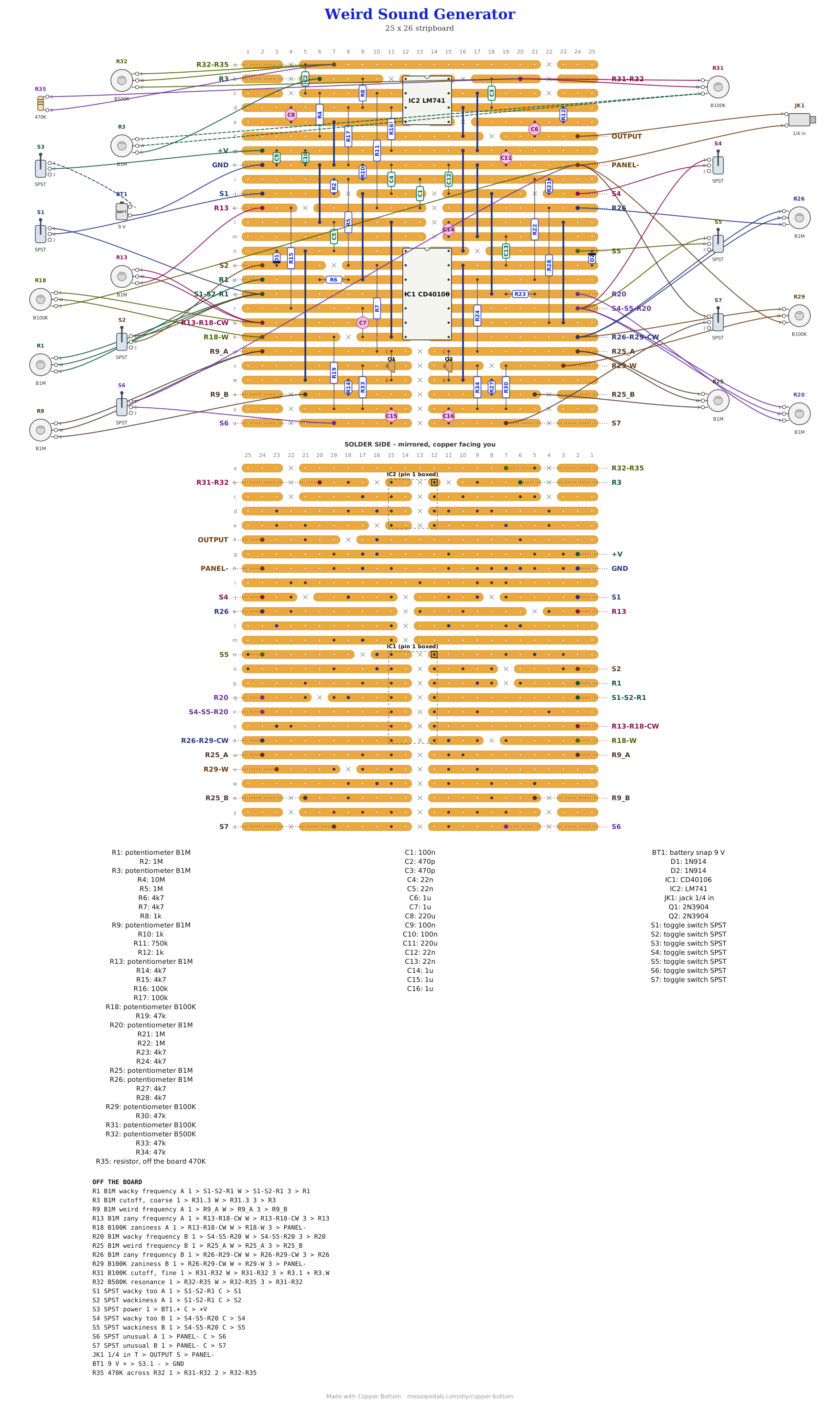
Ray Wilson's Weird Sound Generator is where a huge number of people built their first synth, me included. Ray's page carries a stripboard version by Andrew Sharp, as two pictures. This is that layout as a Copper Bottom file, so the editor can walk you through it part by part, and checked net by net against Ray's schematic. Two voices of three oscillators each on one CD40106, mixed into an LM741 filter, with eleven knobs and seven switches on the panel. Ray's own page, with how it all works in his words, is the MFOS WSG rebuild.
What you'll need
tap to expand / collapse
Ray's parts list, laid out the way the shelf does it. The values are his.
- 1× CD40106 hex Schmitt inverter, 14-pin DIP (IC1) - spot it: CD40106 or 74C14 on top. Not a 74HC14, which Ray rules out. Socket it
- 1× LM741 op-amp, 8-pin DIP (IC2) - spot it: a notch or dot marks pin 1. A TL071 or LF411 drops into the same holes. Pins 1, 5 and 8 are not used, and Copper Bottom lists them as orphans: that is expected
- 2× 2N3904 NPN transistor (Q1, Q2) - spot it: a black half-cylinder marked 2N3904. Emitter, base and collector each have their own strip; the walkthrough names which hole takes which leg
- 2× 1N914 diode (D1, D2) - spot it: a small glass bead with a black band; a 1N4148 is the same. The band faces the switch pad (S2 for D1, S5 for D2), as Ray's schematic draws it. Both stand up
- 4× 1M resistor (R2, R5, R21, R22) - spot it: bands brown-black-green
- 1× 10M resistor (R4) - spot it: brown-black-blue
- 1× 750K resistor (R11) - spot it: violet-green-yellow
- 2× 100K resistor (R16, R17) - spot it: brown-black-yellow. They set the filter's half-rail
- 4× 47K resistor (R19, R30, R33, R34) - spot it: yellow-violet-orange
- 8× 4.7K resistor (R6, R7, R14, R15, R23, R24, R27, R28) - spot it: yellow-violet-red
- 3× 1K resistor (R8, R10, R12) - spot it: brown-black-red
- 4× 22n ceramic (C4, C5, C12, C13) - spot it: 223. The timing caps of the wacky and weird oscillators
- 3× 100n ceramic (C1, C9, C10) - spot it: 104. C9 and C10 are supply bypass caps Ray lists that Andrew's picture leaves out; here they sit across the supply strips
- 2× 470p ceramic (C2, C3) - spot it: 471. The filter's two caps
- 5× 1 µF electrolytic (C6, C7, C14, C15, C16) - spot it: a small can with a stripe down the negative side
- 2× 220 µF electrolytic (C8, C11) - spot it: the two big cans. C11 across the supply is why it keeps singing for a moment after you switch it off
- Stripboard, 26 strips × 25 holes or larger, and solid wire for twelve links
Off the board
- 7× B1M pot (R1, R3, R9, R13, R20, R25, R26) - spot it: the B means linear, which is what Ray specifies for all of them. The frequency pots are variable resistors with the wiper tied to lug 1
- 3× B100K pot (R18, R29, R31) - R18 and R29 are the zaniness dividers, all three lugs; R31 is the fine cutoff, in series with R3
- 1× B500K pot (R32), the resonance
- 1× 470K resistor (R35) - spot it: yellow-violet-yellow. Soldered straight across R32's outer lugs, on the panel, as Ray does it
- 7× SPST toggle (S1 to S7) - an SPDT works as an SPST if you use the middle lug and one end. S3 is the power switch, in the battery's positive lead; Ray calls it Twilight Zone, for what it does when you turn it off
- 1× 1/4 in mono jack, the output
- 1× 9V battery and snap
- Knobs, eleven, and hookup wire: 27 wires leave this board. A metal panel tied to ground grounds the pot bodies, which Ray recommends
The layout file is the guide
Like the rest of the stripboard shelf, the build document for this one is the file itself: ↓ Download Weird_Sound_Generator.json - import it into Copper Bottom and the editor gives you the board picture, the placement walkthrough, the electrical checks and a printable build sheet, all from the same file. No coordinates are written out on this page on purpose: the editor is the viewer, and a number typed twice is a number that can drift.
Comparing it with Andrew's picture? The strips, the cuts and the wiring are his. A few parts stand a hole or two from where his picture has them, on the same two strips, so that every body has room, and C9 and C10 are added across the supply. The two diode bands are set from Ray's schematic: band toward the switch pad.
The netlist
Quoted verbatim from the layout file. It was written from Ray's schematic, not from the board, so when Copper Bottom says the board matches it, that is two separate records agreeing. The capital names are the ones on Ray's PCB, which is how his panel wiring drawing labels every wire.
The off-board wiring
Twenty-seven pads leave the board. The pad names are Andrew's; the MFOS name beside each is the matching point on Ray's PCB, so Ray's panel wiring drawing works for this board as it stands. Lug numbers are Ray's.
| Pad | MFOS | Goes to |
|---|---|---|
| +V | +9V | S3, the power switch; the other side of S3 to the battery's plus |
| GND | GND | Battery minus |
| PANEL- | GND | Ground on the panel: the jack sleeve, lug 3 of R18 and R29, and one side of S6 and S7 |
| OUTPUT | OUT | Output jack tip |
| S1-S2-R1 | WK2A | R1 lug 1 and wiper, and one side of S1 and S2 |
| R1 | WK1A | R1 lug 3. R1 is voice A's Wacky Frequency |
| S1 | DPSA | The other side of S1, Wacky Too |
| S2 | WSWA | The other side of S2, Wackiness |
| R9_A | WD1A | R9 lug 1 and wiper. R9 is Weird Frequency |
| R9_B | WD2A | R9 lug 3 |
| R13 | ZFRA | R13 lug 3. R13 is Zany Frequency |
| R13-R18-CW | ZA1A | R13 lug 1 and wiper, and R18 lug 1 |
| R18-W | ZA2A | R18 wiper. R18 is Zaniness Amount |
| S6 | UNUA | The other side of S6, Unusual |
| S4-S5-R20 | WK2B | R20 lug 1 and wiper, and one side of S4 and S5 |
| R20 | WK1B | R20 lug 3. Voice B's Wacky Frequency |
| S4 | DPSB | The other side of S4, Wacky Too |
| S5 | WSWB | The other side of S5, Wackiness |
| R25_A | WD1B | R25 lug 1 and wiper, Weird Frequency |
| R25_B | WD2B | R25 lug 3 |
| R26 | ZFRB | R26 lug 3, Zany Frequency |
| R26-R29-CW | ZA1B | R26 lug 1 and wiper, and R29 lug 1 |
| R29-W | ZA2B | R29 wiper, Zaniness Amount |
| S7 | UNUB | The other side of S7, Unusual |
| R3 | COF2 | R3 lug 3. R3's lug 1 and wiper go on to R31 lug 3: the two cutoff pots in series |
| R31-R32 | COF1 | R31 lug 1 and wiper, R32 lug 3, and one end of R35 |
| R32-R35 | RES1 | R32 lug 1 and wiper, and the other end of R35 |
How it works, in one breath
Each voice is three Schmitt-trigger oscillators from the one CD40106. The wacky oscillator runs at audio rate; the zany one is slow and wobbles the third, the weird oscillator, through a transistor that shunts its frequency pot, and the zaniness pot sets how hard. The wacky oscillator can join the mix itself (Wacky Too) or gate the weird one through its diode (Wackiness), and Unusual grounds a 1 µF on the way to the transistor's base, so the wobble slurs instead of stepping. Both voices sum into a filter round the LM741, tuned by the two cutoff pots and sharpened by the resonance pot. Ray tells it better, with jokes, on his page.
Things to try
- Ray's mods. The WSG mods page is his; every one of them lands on the same named points, so they apply here
- If it fights back. Ray's troubleshooting page is written for the PCB, and the MFOS names in the table above are how to translate it
- Turn it off while it plays. S3 opens and C11 carries on for a moment, which is why Ray named the switch what he did
The Weird Sound Generator is Ray Wilson's, from Music From Outer Space, 2007 - see the MFOS WSG rebuild. The stripboard layout is Andrew Sharp's, contributed to Ray's page. Traced into Copper Bottom and checked against Ray's schematic by Onion Madder.