Weird Sound Generator (WSG)
Article by Ray Wilson · Music From Outer Space · musicfromouterspace.com
This is a beginner project and I do recommend it as a first project or if you are just getting started in synths or electronics. The circuit, layout and wiring diagram are provided to help you succeed. Please read the entire page before ordering PC boards or kits to ensure that the information provided is thorough enough for you to complete and troubleshoot the project successfully.
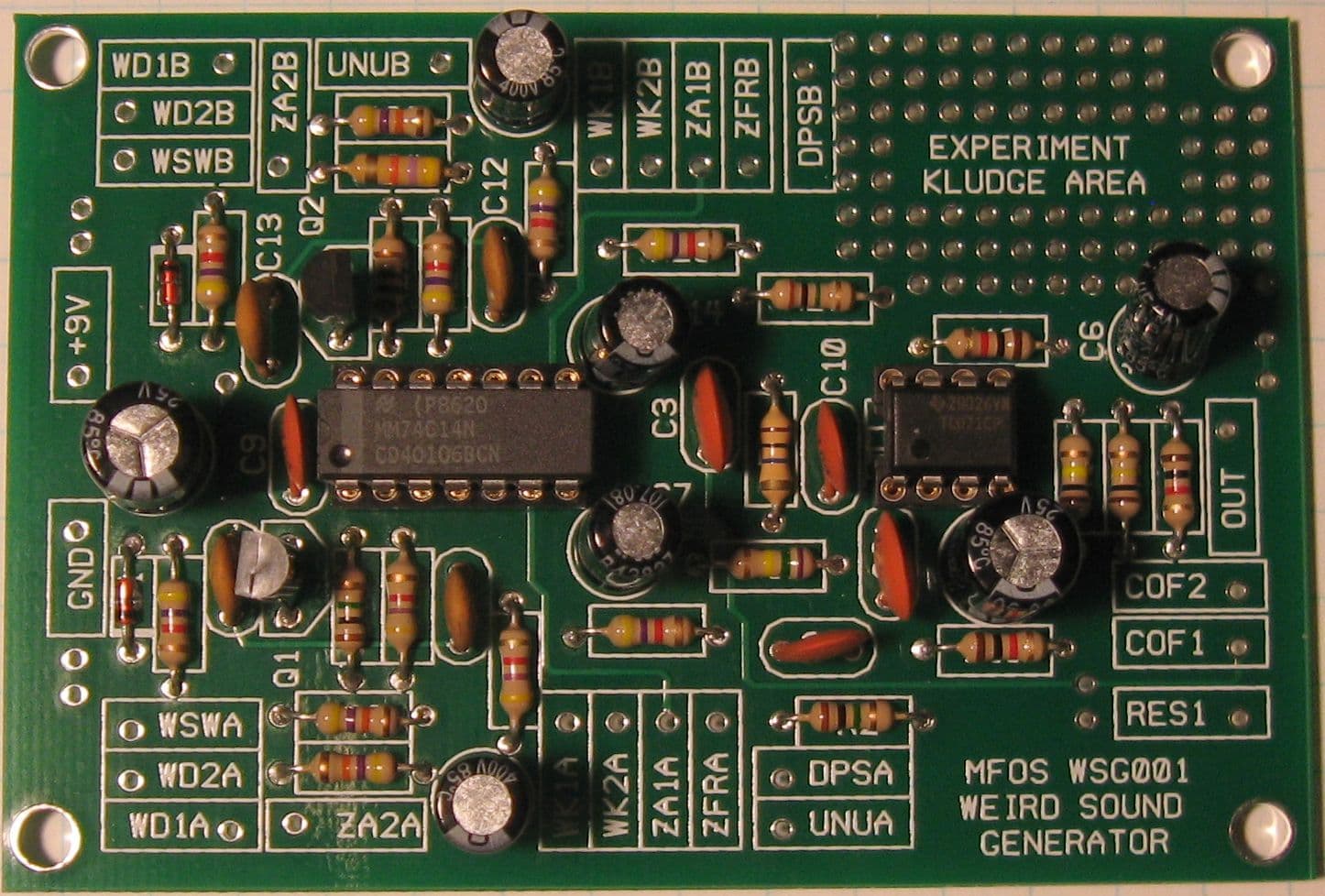
Features
- Makes Wacky, Zany, Weird, Unusual Sounds
- Stimulates brain cell growth in humans and pets.
- Exposure of fetus to Weird Sounds promotes genius and prodigy...ism.
- Can actually get a child away from a television.
- Exposure of octogenarians to Weird Sounds reduces flatulence.
- Fun to do at lunch time, snack time, anytime (low in calories).
- Fun to do at board meetings (or in boring meetings).
- Low current consumption so you can make weird sounds for a long long time.
Introduction
This is a really fun project and it makes a LOT of weird sounds. You will have hours, no at least days... weeks of fun making weird sound after weird sound. You will make at the very least a MILLION weird sounds in the first month alone. I recommend that you use this in conjunction with your hardware or software sampler to provide tons of timbres for you sampling synth. Research by the prestigious Institute or Weirdsoundology at Stockholm has shown that exposure of unborn fetuses to weird sounds promotes genius and prodigy...ism. The following scientific chart makes this point very obvious.
If you don't believe them at least believe me that this is the COOLEST WEIRD SOUND GENERATOR in the near universe. I feel certain that in far away universes there may be others developing weird sound generation equipment and who knows, it MAY be cooler but that would be a stretch.
There is a 5 second delay when you turn the unit on.
Testing in the Weird Sound Labs has shown that there is a five second delay when the unit is first powered. This is due to the biasing network (R16, R17, and C8) charging up until the filter's bias input is happy. Nothing to be concerned about unless an alien is attacking and you know that if you could only hit it with that weird sound you found last night that it would be curtains for the alien. Then five seconds can seem like an eternity and we're sorry.
Sound Tracks For Your Next Independent Film
WSG Concerto Number 1 — realized on the WSG by Ray Wilson. Single track with WSG and reverb added by Cakewalk Home Studio. Faded in the beginning with the Cakewalk Home Studio fade in tool. Multiple knob twiddling and switch flicking employed throughout the piece. (The original audio recordings live on Ray's site, musicfromouterspace.com.)
Obligatory FDA Warning
The Weird Sound Generator you are about to enjoy is EXTREMELY WEIRD and can cause episodes of weirdness, euphoria, gladness, happy times, and things of that nature. Do not attempt to put the Weird Sound Generator into a blender and make a protein shake with it. Do not stand on the Weird Sound Generator in order to reach a high shelf. The Surgeon General has determined that listening to the Weird Sound Generator can cause a disturbance in the force and may result in uncontrollable episodes of performance art. The effects of listening to the Weird Sound Generator while eating a danish have not yet been evaluated (but a WSG and a box of danishes are on their way to the Surgeon General and we expect to hear back soon).
WSG Schematics
The Weird Sound Generator uses technology found at the crash site known today as Area 52 (Anything else is soooo Area 51). The Weird Sound Generator focuses the latent energy of the universe into unusual sounds and lets you hear them for yourself. On a more serioue note the output voltage of the WSG is about 600 to 700 millivolts but can peak as high as 1.5V when the oscillators and filter are resonant. The current drawn averages 4 to 6 milliamps but can peak at about 7.6 milliamps.
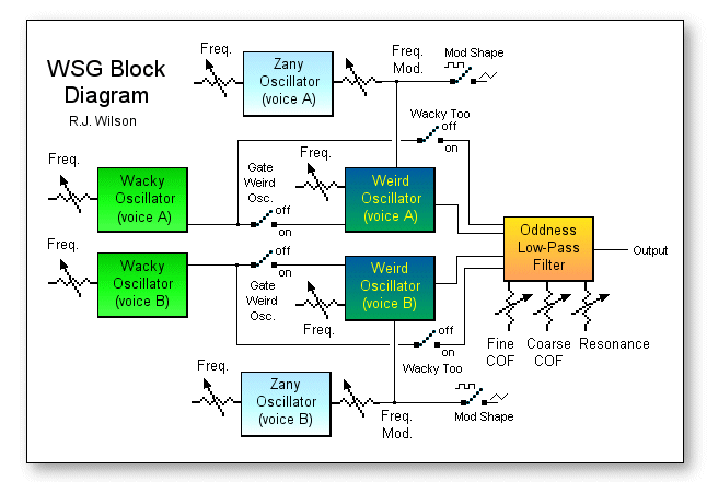
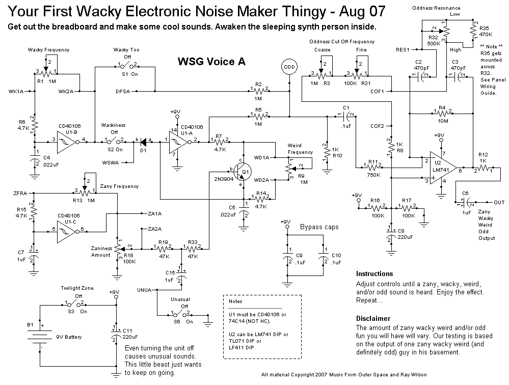
To put it in layman's terms... U1B, R6, R1, and C4 form an oscillator because inverting schmitt trigger U1-B just sits there charging and discharging C4 because when C4 charges up to 2/3 of the supply the output of U1-B goes low and starts to discharge C4 via R6 and R1 ("Wacky Frequency" pot). Then when it gets to 1/3 the supply voltage the output of U1-B goes high and starts charging C4 again and that just keeps happening again and again and again... it's an oscillator (it oscillates... goes up and down). The whole upshot is that U1-B's output goes between logic 1 and logic 0 at a rate set by R1 ("Wacky Frequency"). The rate is audible to us because it's in the audio range. When R1 is adjusted so that there is less resistance between points WK1A and WK2A the oscillator goes faster (higher) and visa versa.
U1-C (along with R15 and R13) is used in the same way only the timing capacitor is much larger and thus the charge and discharge times are longer. It produces the "Zany Frequency". The output of U1-C is a lower frequency square wave. It's output is used to modulate the frequency of the oscillator made up of U1-A, R7, R14, Q1, and R9 (the "Weird" oscillator). Notice that Q1 is shunting (in parallel with) R9 the frequency control for the "Weird Frequency". When current flows through R19 and R33 during the high periods of U1-C's oscillation it turns Q1 on a bit (depending on the setting of R18 "Zaniness Amount") so that during the high periods of U1-C's oscillation the frequency of U1-A's oscillation goes up. During the low periods of U1-C's oscillation the frequency of U1-A's oscillation goes back down (to the frequency set by R9). So you can get that dee doh dee doh type of thing going. Turn the "Zany Frequency" high enough (and the "Zaniness" control up) and you get a kind of bell tone from the oscillator formed by U1-A and associated components.
U1-B and associated components (the "Wacky" oscillator) serves two purposes. It can be added to the audio output via turning the "Wacky Too" switch to on. In this mode both the "Weird" oscillator (U1-A and associated components) and the "Wacky" oscillator (U1-B and associated components) are applied to the input of the filter. You can get some nice beating (tuned close together) or chord (tuned to 4th or 5th) effects like that.
The other purpose of the "Wacky" oscillator is to gate the "Weird" oscillator on an off. When the "Wackiness" switch is On the input of U1-A is brought low during the low part of U1-B's oscillations (via D1). During that time U1-A cannot oscillate. But during the high portions of the "Wacky" oscillator's output D1 is reverse biased and so the input to U1-A ignores U1-B for while. U1-B does not like being ignored but it gets over it pretty fast. The therapy seems to be working. By adjusting the "Wacky Frequency" lower that the Weird frequency and turning Wackiness on you can get a hollow sounding sync effect from U1-A.
The "Unusual" control, when On, causes the signal appearing at the base of Q1 to be integrated (turned into a triangle like wave) so that the Weird frequency goes up and down but glides from high to low instead of stepping as it does when the Unusual switch is Off. This is because when the negative side of electrolytic cap C15 is grounded it takes a bit of time to charge and discharge it via R19. When it's negative side is disconnected from ground it's like it's not even there and U1-C's square wave just plows on through.
The filter is an adjustable low pass with a lot of Q (emphasis of the pass band). The Q can be turned down slightly with the "Oddness Resonance" control. The "Coarse" and "Fine Oddness Cut Off Frequency" controls set the cut off frequency of the filter. When you sweep the filter up you get a kind of wah effect. It is very ringy on purpose to add a lot of harmonic character to the sound. You can Turn the ringiness down with the "Oddness Resonance" control. The "Fine" control is so you can play with the harmonics over a smaller range with more precision.
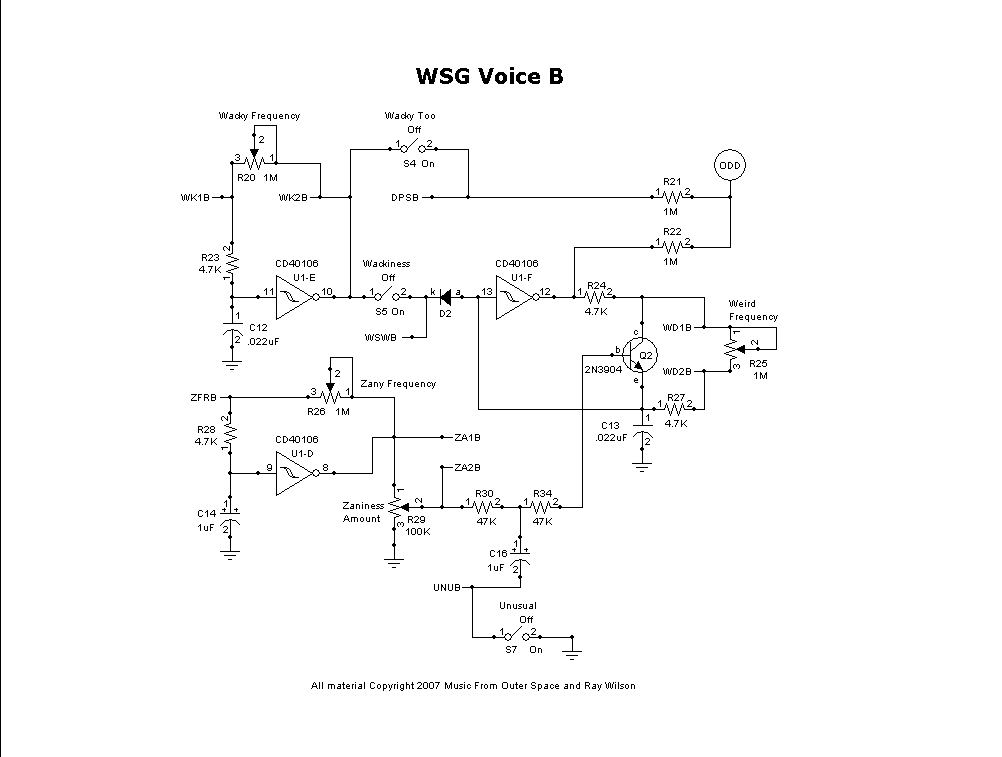
The astute observer has already noted that page two is pretty much the same as the corresponding parts of Page one... sooooo that's that.
Now as I was saying the universal energy that is just flying around wildly during the normal operation of the universe is captured whenever a MFOS Weird Sound Generator is present. The universal energy waves flow into the WSG and then into your brain as you perceive them as sound waves by adjusting the knobs of the WSG. Einstein's theories are rife with information pertaining to weird sounds but I digress. Make one and have fun with it which is positively the lowest part of the bottom line. And don't forget to expose your fetus to the weird sounds and turn them into a genius or a prodigy (or an Einstein if you will). To do anything less would be irresponsible.
The Heart Of The WSG
A Simple "Feedback Around A Schmitt Trigger" Oscillator.
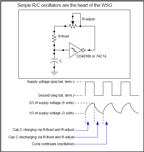
The heart of the WSG is this simple oscillator which is actually in the WSG six times in various forms.
- Two "Wacky" oscillators (sound sources and Weird oscillator gates)
- Two "Zany" oscillators (modulation sources for Weird oscillator)
- Two "Weird" oscillators (sound sources)
When power is first applied to the circuit the capacitor C is in a low state and charges from 0 to 2/3 of the supply (with a 9 volt battery this is 6 volts) at a rate determined by (A) the size of the capacitor and (B) the resistance of R-fixed and the setting of R-adjust. When C charges to 2/3 of the supply voltage the output of the CD40106 snaps from it's current high state (9V) to low (0V). The whole idea of a schmitt trigger is to snap high or low depending on the input voltage. Since this is an inverting schmitt trigger it snaps low when the input exceeds it's high input threshold and low when the input goes below it's low input threshold. Now that the CD40106's output has snapped low, capacitor C discharges at the same rate it charged before to 1/3 the supply voltage (the low threshold) at which time the output of the CD40106 inverting schmitt trigger snaps high again. This cycle continues to repeat and thus we have oscillation.
We use the oscillators in the WSG for sound generation and for modulcation sources. When R-adjust is set to place high resistance between the output of the CD40106 and the capacitor the rate of charge and discharge is low and thus the frequency of oscillation is low. When R-adjust is set to place low resistance between the output of the CD40106 and the capacitor the rate of charge and discharge is high and hence the frequency of oscillation is high.
PC Board Layouts
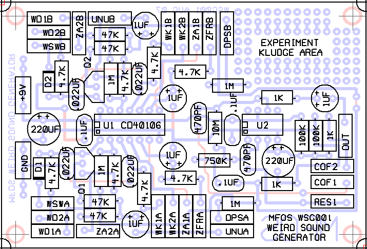
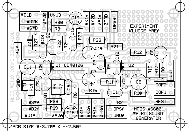
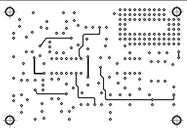
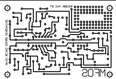
The parts layout, silk screen and copper artwork for the MFOS PC board. Print the parts layout (values shown) and use it to check off every component as you populate the board.
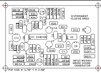
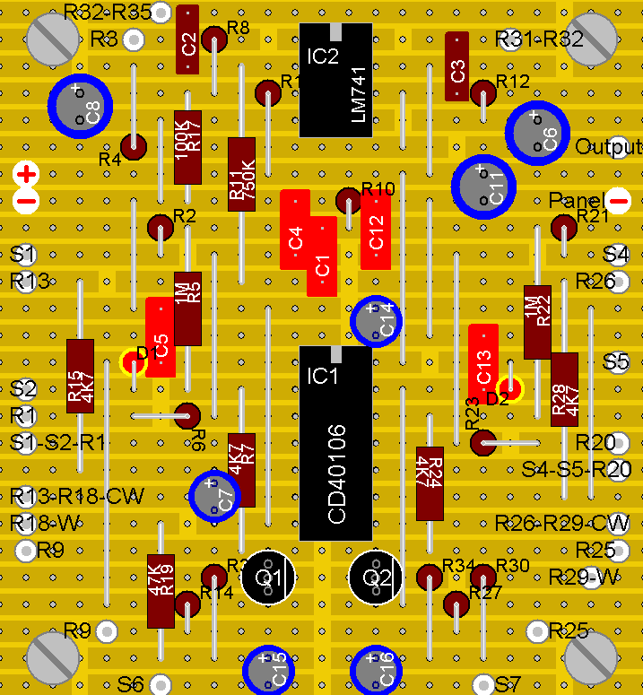
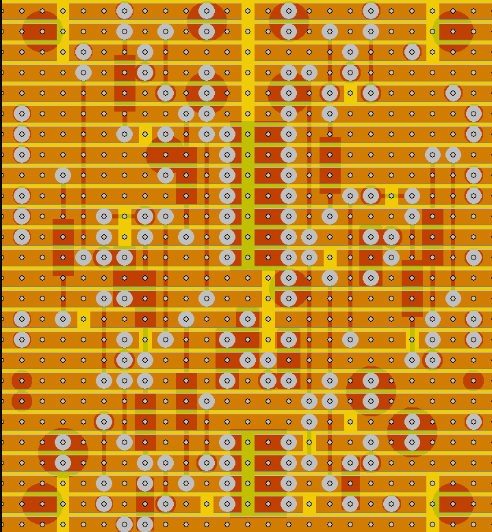
Stripboard layout (by Andrew Sharp)
A stripboard (veroboard) version of the WSG layout, contributed by builder Andrew Sharp.
CHECK YOUR 1/4" PHONE JACK'S TERMINALS — THEY ARE NOT ALWAYS THE SAME!
Phone jacks sometimes have the tip and sleeve terminals in different positions on the jack. This is often the case when the jack includes a switch and thus has more than two terminals. To make sure your WSG makes "weird" sounds and not "no" sounds be sure to connect the jack's "tip" terminal to the output (OUT) of the WSG and the jack's "sleeve" terminal to the WSG's ground (GND).
If you are not getting output from the WSG make sure to use your ohm meter and "ring out" the jack to make certain of which terminal is which. Make sure that if there is a switch on the jack (indicated by three solder terminals and a flap of metal up against the tip connector) that you are not fooled since it is typically shorted to the tip connector unless the phone plug is inserted and then it is not contacting the tip connector. So... if you connect OUT to the switch leg and plug in the jack... no sound. Make sure you connect the OUT of the WSG board to the tip connector's terminal.
Some Wiring Advice
IMPORTANT! While recently building some WSG units I found that it is important to keep the three wires that control the filter cut-off frequency and resonance (RES1, COF1 and COF2) away from all the other wires that carry high level rectangle wave signals. This is because these three wires (RES1, COF1 and COF2) are part of the high gain filter circuit and are susceptible to having adjacent wires capacitively couple signals into them.
Give your Wacky, Zany, Weird, Odd Sound Generator that "Professional" look
When you show up at the board room of your next stock holders meeting with a weird sound generator built into a shoebox, don't count on that elusive promotion you've been tacitly pursuing. However, if you show up with your WSG built into a nice case with this professionally manufactured front panel with a silk screened legend don't be surprised if you are asked to stand and open the meeting with a recitation of the company mission statement while accompanying yourself on the WSG (don't forget your amp).
This completely cool front panel is made of 1/16" thick aluminum plate that has been sheared, punched, deburred, and silk screened all for the purpose of helping you make your WSG project go smoothly.
There Are Two Panel Styles in Production
Either of these panels are perfect for holding the panel components of the WSG and we will send the one we have in stock at the time of your order. It is important to note the difference in the panel mounting hole locations and take it into consideration when you are building the case for your unit.
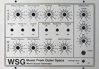
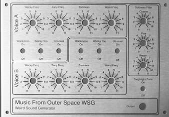
Panel Type 1 Wiring Diagram
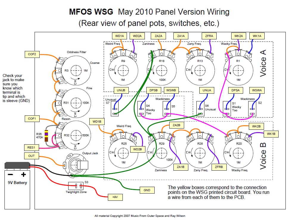
PLEASE NOTE! Resistor R35 (470K) is mounted on the front panel, not on the PC board.
Panel Type 1 Legend Template
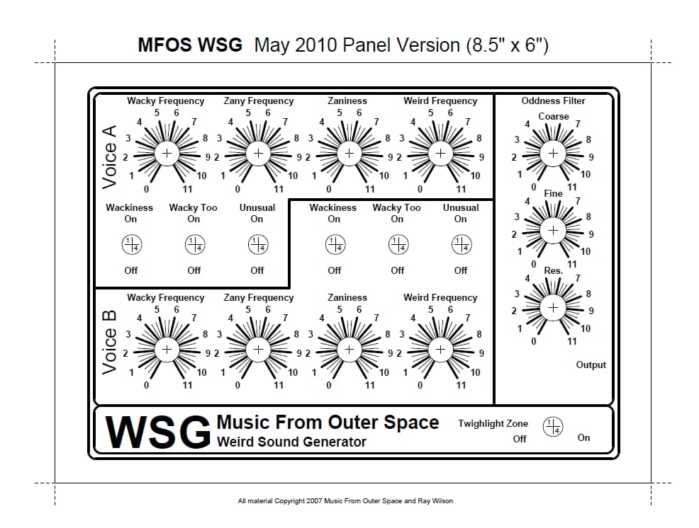
Panel Type 2 Wiring Diagram
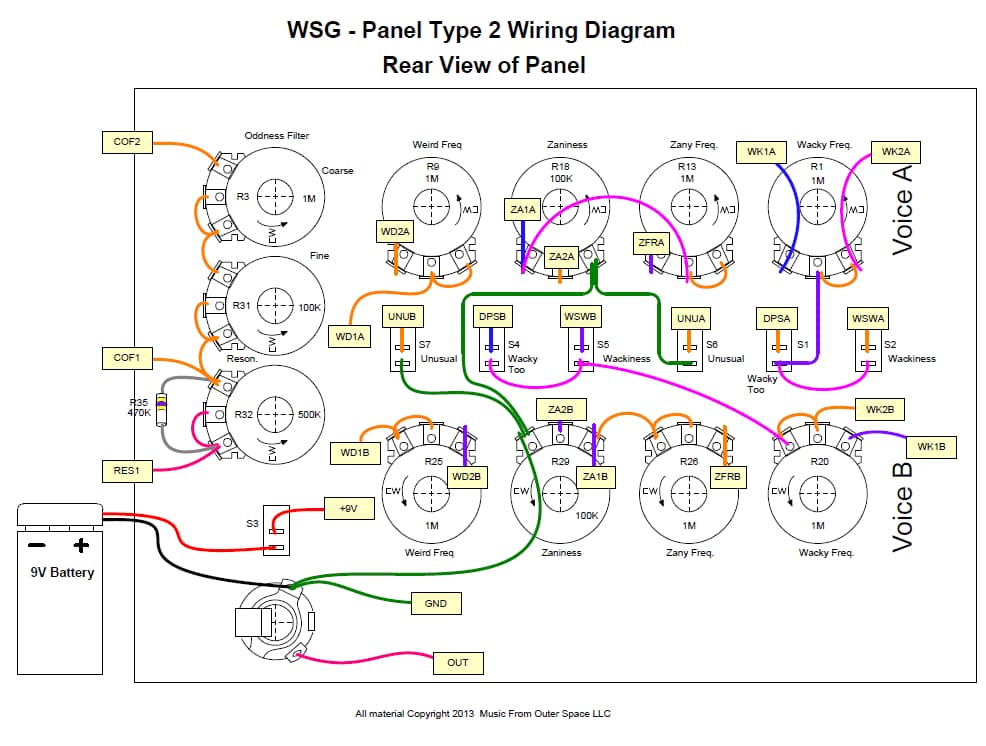
PLEASE NOTE! Resistor R35 (470K) is mounted on the front panel, not on the PC board.
Panel Type 2 Legend Template
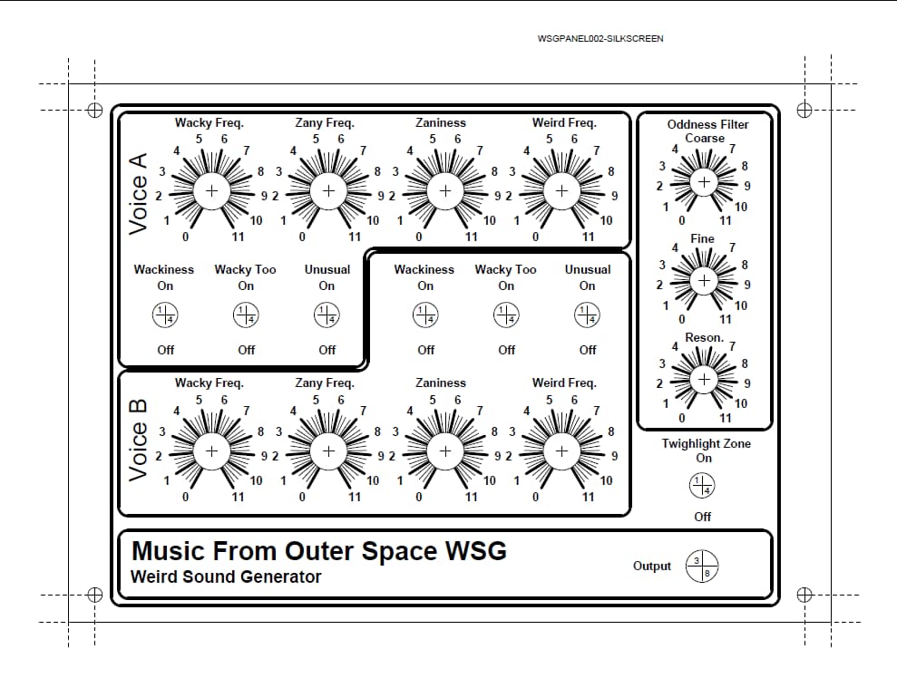
Making Your Own Panel and Case
Why Use Metal For The Panel..?
I recommend using a metal front plate for the pots and switches so that by connecting it to the ground of the unit (battery negative - NOT EARTH GROUND) the pot bodies get grounded since they are in direct contact with the front plate. The ground I show in the panel diagram "Connect Chassis to Ground" is just a piece of tin plated ferrous metal (solderable) that is bolted to the metallic front panel. You can't solder to aluminum. You can buy these at Radio Shack and other electronics stores.
If you don't use metal for your front panel then I suggest you line the inner surface with aluminum tape used by the heating and cooling people. When the adhesive side of this tape is stuck to the non-adhesive side (as when you cover a large area with several pieces and overlap them) the pieces conduct to one another very well. You do want to rub them down well and BE CAREFUL NOT TO CUT YOUR FINGERS as the edges can be sharp (wearing gloves is a good idea). Once they are connected my meter reads very low resistance between pieces (the same as when the leads are shorted). In my book that's pretty darn connected. You still want to bolt a solderable terminal to the front panel which is in contact with the aluminum (you can't solder to aluminum) and connect it to the circuit ground. Then you use an exacto knife to cut out the panel holes and mount your hardware. Voila... all of the pot bodies will be electrically connected to one another and to the circuit ground. I use 1/8" Masonite for prototype front panels and use the tape method to shield and ground the front panel components.
The reason you want to do this is because some points in the circuit are fairly high in impedance and the pot bodies can pick up and induce electromagnetic interference into the circuit and cause 60 cycle hum if they are not in contact with the circuit ground.
How To Make A Simple Case For The WSG
(These drawings are NOT for the panel sold above.)
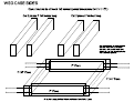
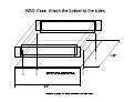
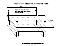
These diagrams show how to make the case and how to mount the PC board to the case. What you want to do in roughly this order is this:
- Make the parts of the case and paint it (if desired).
- (optional) Print out and laminate the front panel drawing at an office supply store.
- Print out the front panel, trim it and then glue it to the top of the case lined up with the holes.
- Cut holes in the overlay corresponding with the holes in the front panel.
- (optional) If you used non-conductive material for the front panel then use aluminum tape (usually found in the heating and cooling section of the hardware store) to laminate the inside of the front panel.
- Mount the components to the front panel (just poke them through the aluminum tape if you used it). If you did not use conductive material or aluminum tape I suggest you at least connect the pot bodies to ground. Maybe the sounds are even weirder without this... you be the judge.
- Do the intra-front panel wiring (kit buyers... be frugal with the wire as 24 feet goes quicker than you think).
- Populate the PC board with components.
- Lay the top up-side down to the side of the case (as if you had opened the case to the side) and the PC board near where it will be mounted and run the wires from the front panel components to the PC board keeping in mind that you will want to fold up the wiring when you are ready to attach the PC board to the bottom of the case and close it. (again kit buyers... be frugal with the wire as 24 feet goes quicker than you think).
- Attach the battery.
- Connect the battery and make weird sounds until your heart is contented.
More Panels From Other Creative Builders
- Kristian Bauck-Nordeide's Modified Panel
- Clay Roe's Sputnik Panel Design (5.4M PDF)
- Michal Skarzynscy's Picnic WSG Front Panel
(These builder panels are hosted on Ray's original site.)
Helpful Hints From Kit Builders
- WSG Construction Guide by Simon Gains
SPDT switches which work perfectly as SPST
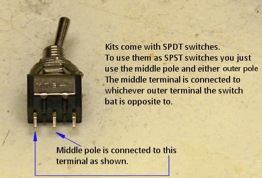
Single Pole Double Throw Switches serve perfectly as SPST switches. As you can see in this image the switch has three terminals. The middle terminal is common and is connected to either of the outer terminals depending on the position of the switch bat. The terminal that is opposite of the way the switch bat leans is the terminal in contact with the middle terminal. Either outer terminal can be used.
Battery Snaps
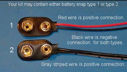
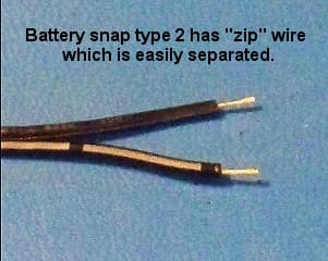
We ship two types of battery snap. One has red and black wire (type 1) and one has two black wires with one of them imprinted with a white broken stripe (type 2). With the red and black type the red is the positive connection. With the two black wire type the one imprinted with a white broken stripe is the positive connection. The type 2 snap (two black wire) has "zip" wire which can be separated easily by simply pulling the two wires apart near the stripped end.
How To Remove Break-off Lock Tabs From Your Potentiometers
If your pots have little tabs on them you will need to remove them so that you can mount them to your faceplate. It is really easy to do. Carefully snap off the little tab near the pot body and voila it's done. Some kits come with larger pots and some kits come with smaller pots. The smaller pots are at times more expensive than the larger pots. They're all good quality pots and they all work the same way.
Regular Sized Pots
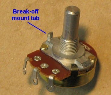
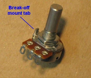
This is the break-off lock tab which can be used to keep the pot from turning when you turn the pot shaft but tightening the mounting nut works just fine. If you have the wherewithal to drill little holes for these pesky things... be my guest. If not... read on.
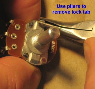
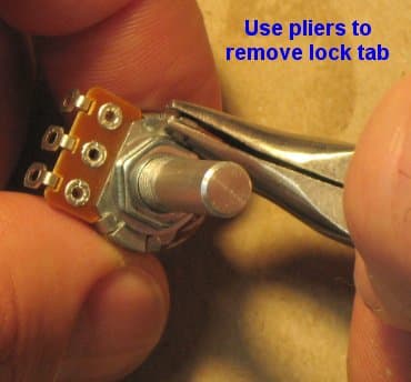
Using pliers, grasp the tab as low on it as you can and then gently twist the pliers outward. I told you it was easy.
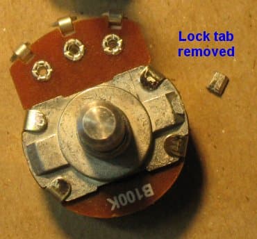
The little broken off tabs look like this. Now you can mount your pot without the little tab getting in the way.
Smaller Sized Pots
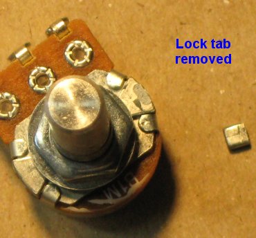
WSG Parts List
Obtaining Parts
Kits and components for your MFOS projects can be found at Small Bear Electronics and SynthCube. The potentiometers can be rated for 1/4W and the parts list will say whether it should be log or linear taper. All components need to have leads. Be sure you are not buying surface mount parts.
Resistor Color Chart For Resistors Used In This Project
The resistors should be carbon composition or carbon film. Use 1/4 watt resistors because 1/2 watt will be too big for the board.
| Value | 1st band | 2nd band | 3rd band |
|---|---|---|---|
| 1K | brown | black | red |
| 100K | brown | black | yellow |
| 470K | yellow | violet | yellow |
| 10M | brown | black | blue |
All work © Ray Wilson / Music From Outer Space - musicfromouterspace.com. The Weird Sound Generator, its circuit, text and images are Ray's.
Mirrored and recoded by Mess O' Pedals to preserve Ray's work and keep it accessible. Only the HTML is mine - the WSG, the words, and the wit are all Ray Wilson's.