Hive Drone
Six 40106 voices on one board, drawn in Copper Bottom · By Onion Madder · Mess O' Pedals
This is the Dead-Bug Hive grown up and soldered down. Same idea: one CD40106 holds six Schmitt inverters, each one turned into an oscillator by a cap and a resistor, and each one given its own pitch knob. What changes is the cap - one per voice, stepping a decade at a time from 100pF to 10 µF - so the six run from a thin whistle at the top to a slow tick at the bottom, and everything in between beats against everything else. Six knobs, one output, no chips but the one.
What you'll need
tap to expand / collapse
Same parts as the dead-bug build, laid out to be soldered once instead of dangled.
- 1× CD40106 (a.k.a. CD40106B / MC14106) hex Schmitt inverter, 14-pin DIP - spot it: CD40106 printed on top, and a notch marks pin 1
- 6× ceramic capacitors, one per voice - the whole ladder: 101 (100pF, the top whistle), 102 (1n), 103 (10n), 104 (100n), 105 (1 µF), 106 (10 µF, down at a tick). Spot it: the three-digit code is the value - first two digits, then that many zeros, in picofarads
- 6× 1K resistors, one per pot, in series with it and not optional - bands brown-black-red-gold. At 0 Ω an inverter's output ties straight to its own input and the voice dies into a dead short
- 6× 10K mixing resistors, one per voice - bands brown-black-orange
- 6× 1 µF mixing capacitors, one per voice - NP / bipolar, and the layout file marks them that way so the editor asks for the right part. Audio swings both ways, so a polarized can here is sitting backwards half the time. Spot it: an NP can has no stripe down its side, and usually says NP or BP on it
- 1× 100n ceramic (printed 104) and 1× 100 µF electrolytic - supply decoupling, across the V+ strip
- 1× 10 µF electrolytic - the output DC blocker. Spot it: the stripe marks the minus leg, and the longer leg is plus
- 1× 1K resistor for the output, and a jack to an amp - or feed the Dead-Bug Hornet and get a speaker
- 1× stripboard, 13 strips × 19 holes or larger
- Solid-core hookup wire for two links, soldering iron, track cutter, multimeter
Off the board
- 6× 1M pots, one per voice, off-board - spot it: pots are marked with their taper then their value, so B1M is the linear one you want. Wired as a variable resistor: wiper plus one outer lug, third lug left empty
- 1× power source - at least two vape cells in series (7.4V; three gives 11.1V), or a 9V battery
- 1× 1/4″ jack - tip to OUT, sleeve to GND_JACK
- An SPST toggle for power, in the positive supply lead between the DC jack or battery and the board's supply pad. Not in the layout file - it is off the board, and every build on this shelf gets one
The layout file is the guide
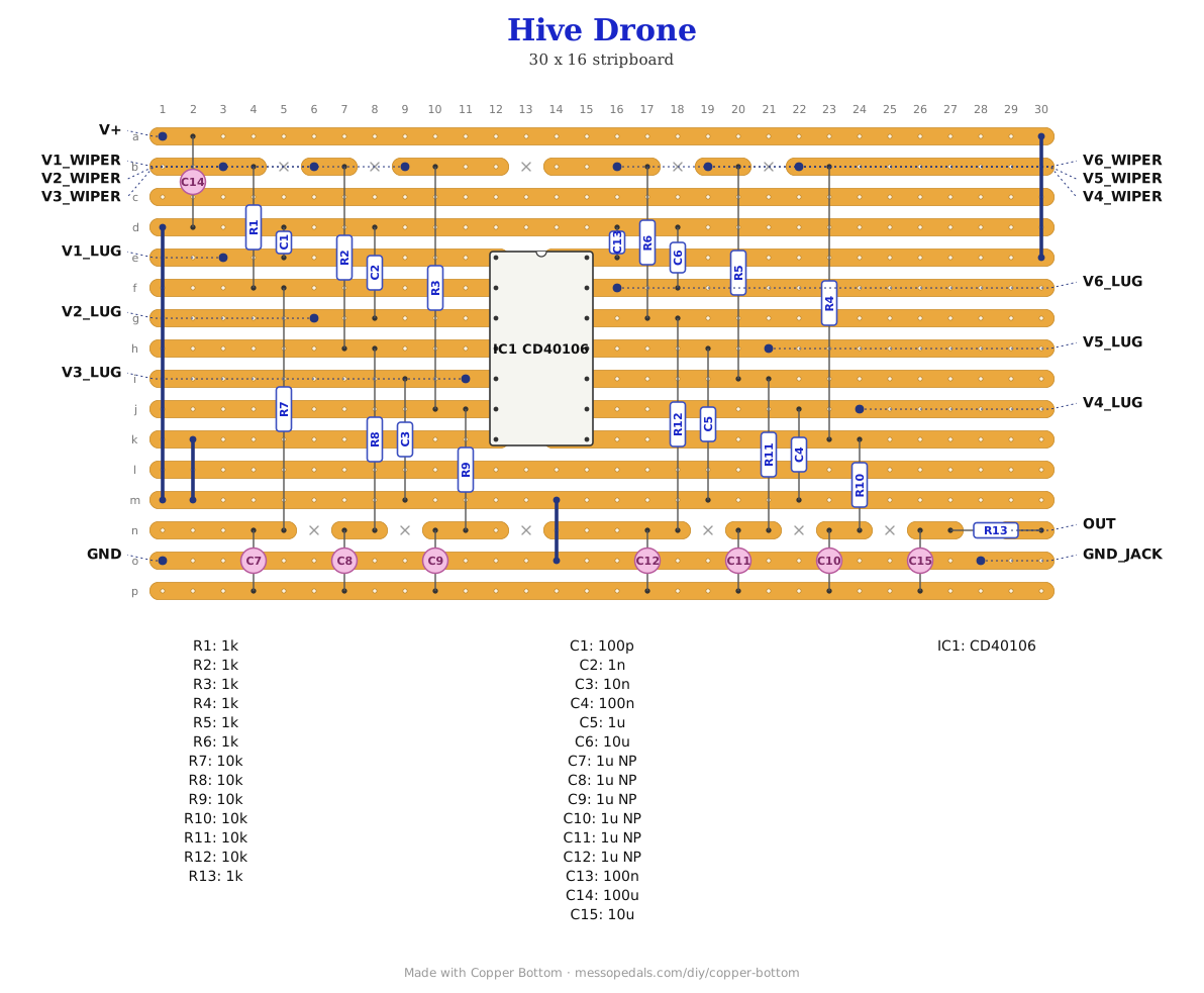
Like the 555 theremin and the Opto Duet, the build document for this one is the file itself: ↓ Download Hive_Drone.json - import it into Copper Bottom and the editor gives you the board picture, the placement walkthrough, the electrical checks and a printable build sheet, all from the same verified file. No coordinates are written out on this page on purpose: the editor is the viewer, and a number typed twice is a number that can drift.
The netlist
Quoted verbatim from the layout file. This one was written from the board rather than before it, so checking the board against it can only pass - what it is for is carrying the circuit somewhere else, and telling you what every strip is supposed to be doing while you stare at it.
The off-board wiring
Sixteen pads leave the board. Twelve of them are the six pitch pots.
| Pad | Goes to |
|---|---|
| V+ / GND | The supply. 9V battery or a vape pack; a 40106 is happy from about 3V to 15V. The 100 µF and the 100n both sit across it on the board, so nothing extra is needed at the battery end |
| V1_WIPER … V6_WIPER | The middle lug of each pitch pot. On the board this pad already has that voice's 1K sitting between it and the inverter's output, so the 1K is done for you - do not add another |
| V1_LUG … V6_LUG | Either outer lug of the same pot. Which one you pick decides which way the knob raises the pitch, and that is the only difference - so pick one, wire all six the same, and the six knobs turn together. The third lug stays empty |
| OUT | Jack tip, through the 1K that is already on the board. The 10 µF before it blocks the DC, so this is a clean line-level-ish output into an amp |
| GND_JACK | Jack sleeve. It is the same net as GND - it is a second pad so the jack gets its own wire home instead of sharing the supply's |
Each pot is a variable resistor, not a divider. Two connections only, wiper and one outer lug, and the third lug is left bare. That is the same wiring as the Hive's pitch controls and the opposite of a volume pot, where all three lugs are used and the point of it is being able to reach silence. Here reaching zero ohms would tie an inverter's output to its own input, which is why the 1K is on the board and why it is not optional.
Built, and heard
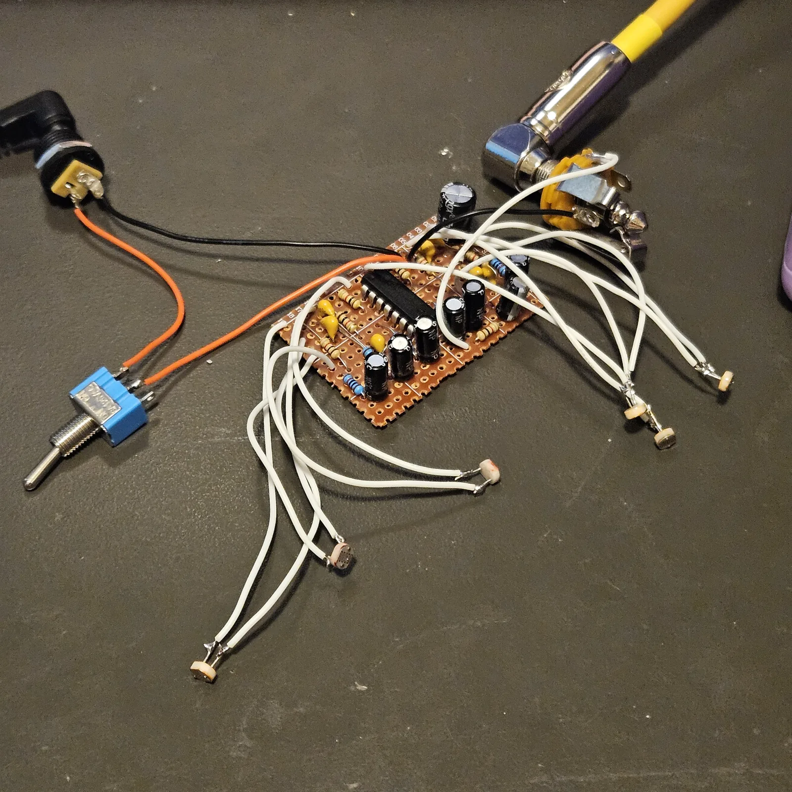
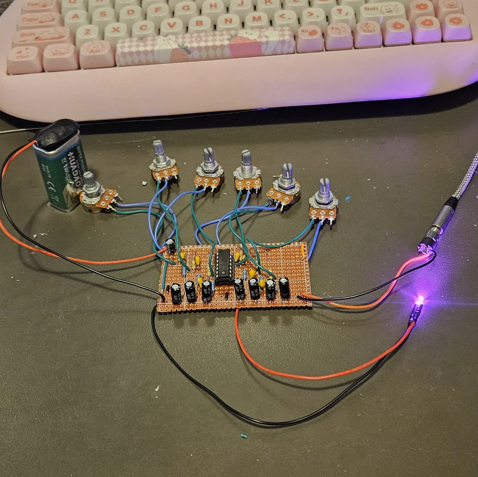
Built on the bench in September 2026, straight off the first drawing of this board - 16 strips by 30 holes, kept here as Hive_Drone_v1.json - and all six voices sing. The 13 by 19 file above is the same circuit on less copper, every net checked against the built board, and I have built that one too, in October 2026, with six photocells (LDRs) in place of the pots. It sounds like a swarm of bees, really wobbly. The first board took two goes. The first build brought up only half the voices, with the copper checking clean - the netlist and the board agree across 29 nets and 86 connections, nothing shorted, nothing floating - so the fault was off the board, where the file cannot see: twelve of the sixteen pads are the six pitch pots, and a pot is three lugs of which only two are used. It came apart for a pot rewire, and this is the board that came back together. In the photo the pots, the battery and the output lead are still on flying leads, and the lit LED is not in the layout file. Not boxed yet; the drill templates below are still proposals.
How it works, in one breath
A Schmitt inverter flips its output when its input crosses a threshold, and it has two thresholds - a high one going up and a low one coming down. Hang a cap from the input to ground and run a resistor from the output back to the input, and the thing chases itself forever: the output sits high, so the cap charges through the resistor until it crosses the top threshold, the output flips low, the cap drains back down through the same resistor until it crosses the bottom one, and around again. The cap sets the range and the pot sets the pitch inside it.
Six of those live on one CD40106, and they are not synchronized to anything, so they drift against each other and beat. Each output goes through its own 10K and 1 µF into one shared strip, which is the whole mixer - six resistors meeting at a point is a passive summing junction, and it costs nothing. Then a 10 µF blocks the DC and a 1K takes it to the jack.
The right-hand gates read backwards. On the left of the chip, input then output goes 1-2, 3-4, 5-6, so the numbers climb. On the right they run the other way: the output is the LOWER number every time - 8 is a voice's output and 9 its input, 10 and 11, 12 and 13. The layout has this right, but it is the single easiest thing to mis-wire when you are checking a voice with a meter and expecting the pattern to hold.
↓ Same box, jacks on top (PDF)
The second sheet keeps every control where this one has it and moves the jacks - power and audio - to the top wall, so the cables leave upward. Two ways to drill one box; pick one.
Six pitch pots in two columns of three, reading in pairs. Twenty-one millimeters between centers is all there is, so small knobs are not optional.
Print at 100% / “Actual size”, never “Fit to page” - check the bar measures exactly 4″ before you touch a drill. The face is 66 by 121 mm but only 42 mm of it is drillable once the lid lip is clear.
Nobody has drilled this one yet. The hole sizes come from the layout file; where they sit is this format applied to it. Offer the sheet up to the box and check it against your own parts before you make a hole.
Things to try
- Change the ladder. The decade steps are a starting point, not a law. Six caps closer together give you a tight cluster that beats hard; six further apart give you a chord with an LFO on the bottom.
- Let the bottom voice modulate the others. The 10 µF voice ticks below hearing. Its output pad is already on the board, so a wire from there into another voice's input turns that voice into a siren.
- Photocells instead of pots. The pitch pads take any resistance, so a cell in place of a pot makes a voice you play with your hands - the same trick as the 555 theremin. Keep the 1K. My 13 by 19 board runs on six of them.
- Switch voices out. A switch in series with a voice's 1 µF mixing cap mutes just that voice and leaves it running, so it comes back wherever it has drifted to.
Circuit after the classic 40106 oscillator bank, the same one behind the Dead-Bug Hive. Layout drawn by Onion Madder in Copper Bottom.