PCB · CD4017 + NE555
Spider Sequencer PCB v1.1
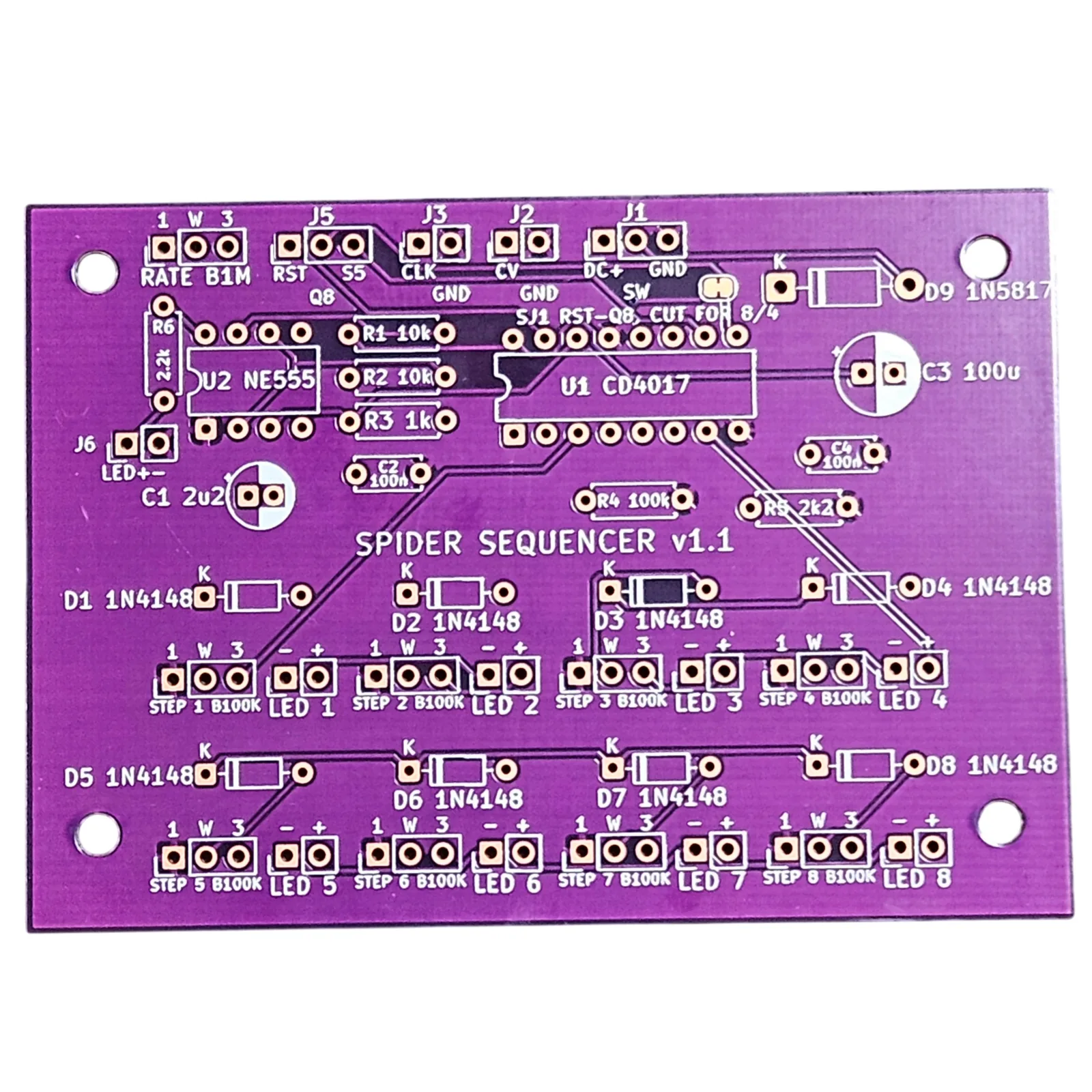
The Spider Sequencer on its v1.1 board. A 555 clocks a CD4017 through eight steps, each step has its own knob and its own LED, and the eight knobs share one CV output through a diode each. On this board all nine pots and all eight LEDs go on the face on wires, each from a header of its own.
Nobody has built one of these boards yet, me included. The circuit is built and working: it is my Spider Sequencer PCB, the v1.0 board. This is its v1.1 redraw. If you build one before I do, I would love to hear how it went.
- Buildsthe Spider Sequencer PCB v1.1 guide, free to read first
- Board82 by 58 mm, two layers, every part's number and value printed on it
- ChipsCD4017 + NE555
- Power9V DC, center negative
- SolderingYes: every part goes through the board
- Comes withThe board only. No parts, no enclosure
- StatusBoards made, none built yet
The bare board. You bring the parts; the guide has the full list.
Read the build first
The whole build is free on the Spider Sequencer PCB v1.1 guide: the parts list to print, what goes on each header, the build order, and a drill template for the box. The board comes bare, so read the list before you buy and you will know what else you need.