MFOS Mini 3-In Mixer & 1W Amplifier
Article by Ray Wilson · Music From Outer Space · Revision 02
This project results in a cool little battery powered amplifier you can use to show your friends what your project sounds like and you won't even need an outlet. Three inputs, a tiny mixer, and a one-watt LM386 amp — just enough to show off a synth.
Features
- 9V Battery Powered
- 3 Input Mixer
- 1W Output Power
- Very Simple Circuit
Introduction
This project results in a cool little battery powered amplifier you can use to show your friends what your project sounds like and you won't even need an outlet. Since it runs on one 9V battery it's perfect for the coffee shop, lunch room, picnics, company picnics (an entirely different affair), scenic outings, other outings, mountain climbing expeditions, sky-diving, quiet sound-ins, quiet rap battles, moon landings and many other situations that I can't think of right now but I hope you do.
I do not recommend the amplifier for: large public address systems, stadium concerts, loud rap battles, booming bass, protest marches, quiet mountain climbing expeditions, quiet picnics, quiet scenic outings. Do not use the amplifier in the confessional, at solemn religious observances, at the library, during church, at meetings concerning announcements about the findings of the LHC at CERN, or at sensitivity sessions where everyone is being quiet. If the sensitivity session gets out of hand you may need to somehow calm the group with the amp and your synth... but I have no ideas about how that might go.
This is not a loud amplifier. It's a wee baby of an amplifier with just enough volume to show off your projects.
Ch-ch-ch-changes
Circuit Description
The LM386N-4 is the mainstay of this project. It is a monlithic 1W amplifier in an 8 pin DIP that has been around since the 1970s. It requires very few parts and runs on one nine volt battery.
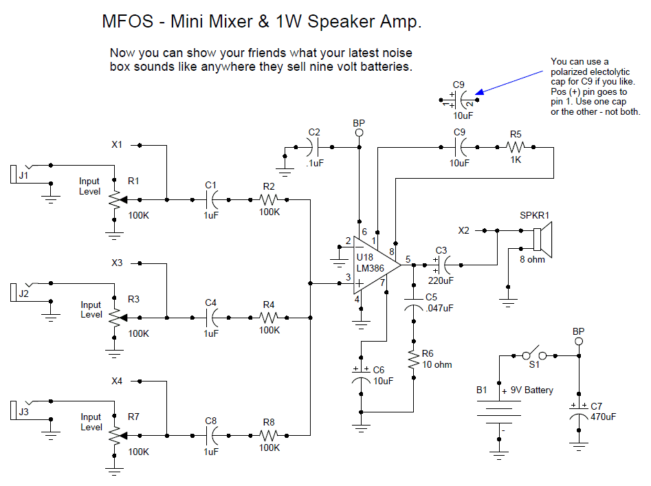
The inputs go from the tip connectors on jacks 1, 2 and 3 to the input level controls. R1, R3 and R7 (all 100K linear potentiometers) are used as variable voltage dividers for adjusting the input levels. The signal at the wiper of each pot is fed via a series connected 1uF bipolar (non-polarized) capacitor (C1, C4 and C8) and a 100K resistor (R2, R4, and R8) to the non-inverting input of the LM386N-4 (pin 3). An internal 50K resistor in the LM386N-4 holds the non-inverting input to ground when no signal is present. Capacitor C2 (.1uF ceramic) and C6 (10uF electrolytic) bypass the amplifier chip to improve performance.
The gain of the amplifier is normally 20 with no additional gain altering components placed between pins 1 and 8. We push the gain to about 50 by inserting C9 (10uF bipolar cap) in series with a R5 (1K resistor) between pins 1 and 8. The lower we make the gain set resistor the higher the circuit's gain. The maximum gain is 200 when using a wire jumper instead of R5 (1K gain set resistor). If used with high gain setting at high output levels the battery will discharge more quickly.
A polarized cap can be used for C9. If used the positive side of the cap should be installed so that it is connected to pin 1 of U18 (LM386N-4). I had named the LM386N-4 U1 but it insisted on being called U18. Some chips are real smart alecks.
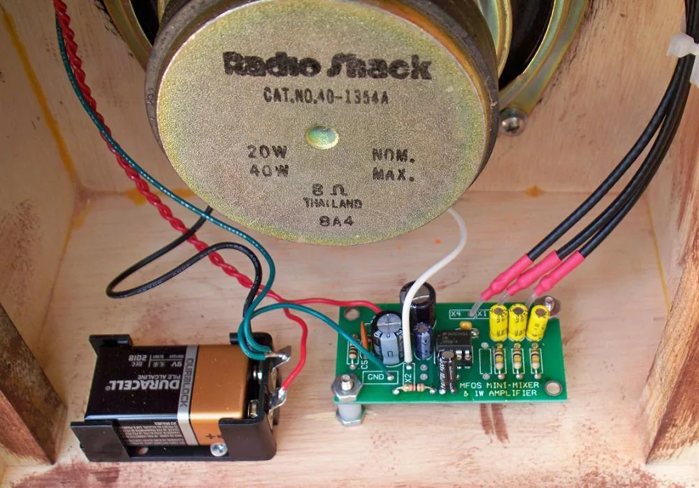
Capacitor C5 (.047uF) and resistor R6 (10 ohm) stabilize the amplifier's output. Capacitor C3 (220uF electrolytic) is used to couple the amplifier's output to SPKR 1 (8 ohm 1W or greater) speaker. I used a 5" 8 ohm 20W speaker I got from Radio Shack but any 8 ohm speaker will do. Don't go too big because 1W of power can't push a very large cone around.
The battery is switched via S1 to the circuit and is bypassed with capacitor C7 (470uF electrolytic). The battery won't last a long time when used at high output levels (high relative to the unit - as I said it's not super loud) but should get you through a coffee shop synth demo or two.
Schematic
PC Board Information
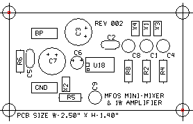
Parts Layout With Component Designators
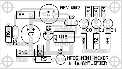
When you are trouble shooting you'll need this view so that you can refer between the designators and the components shown in the schematic.
C9 is specified in the parts list as a non-polarized 10uF aluminum cap but you may use a polarized electrolytic if you like. If you use a polarized electrolytic cap for C9 be sure to install it so that the positive side is inserted in the pad shown with the red circle in the image.
Parts Layout With Component Values
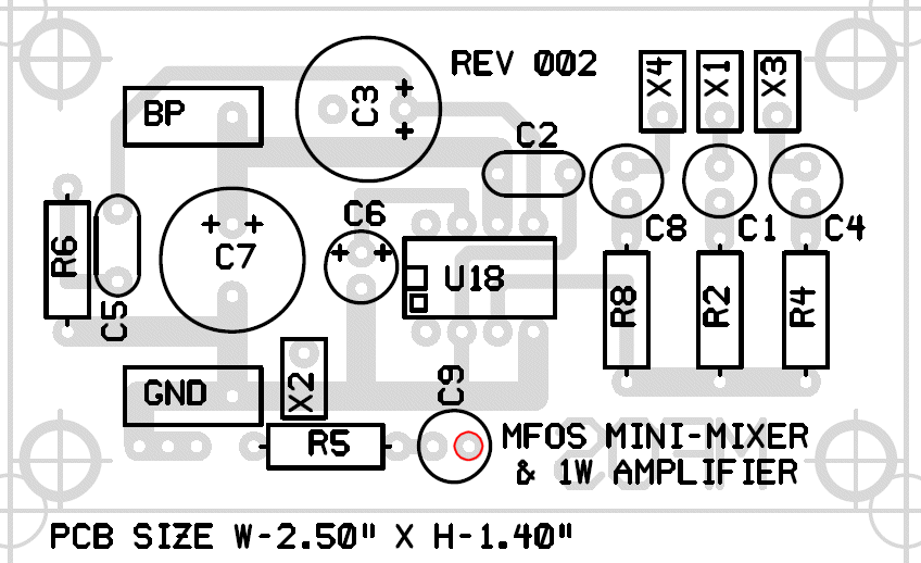
Print out this view to use when you are populating the PC board. Not having to continually refer between designators and the schematic will save you a lot of time.
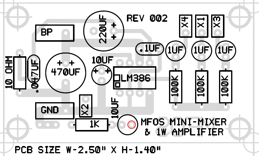
Top Copper
MFOS PCB Images are as viewed from the top of the PC Board. Keep that in mind when you are using the patterns with photo or copier processing.
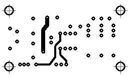
Bottom Copper
MFOS PCB Images are as viewed from the top of the PC Board. Keep that in mind when you are using the patterns with photo or copier processing.
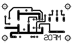
Silk Screen
MFOS PCB Images are as viewed from the top of the PC Board. Keep that in mind when you are using the patterns with photo or copier processing.
Front Panel Information
Suggested Front Panel Layout & Wiring
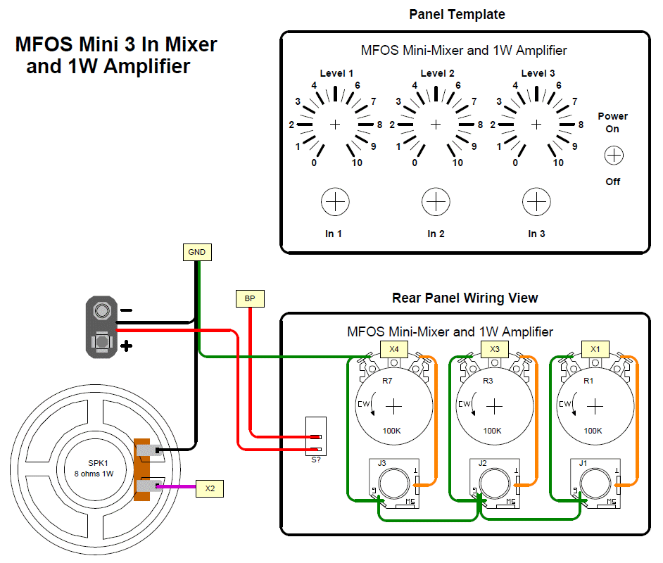
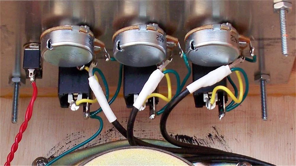
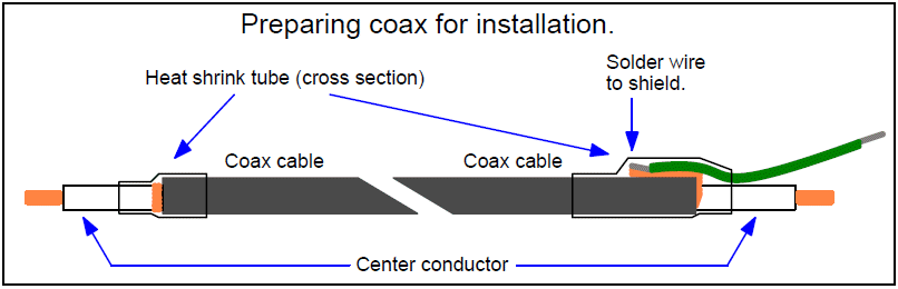
I ran coax cable from the pot wipers to the PC board points X1, X3 and X4 to keep EMI noise to a minimum. I only grounded the coax shield on the panel side. I prepare the coax so that the ground shield doesn't end up shorting to anything as shown below. On the board side the shield is entirely insulated with heat shrink tubing and the center conductor is connected only.
Here is how I prepare coax wire. The heat shrink keeps stray ground wires from getting loose and causing havoc.
Images From My Build
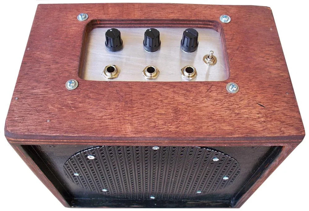
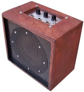
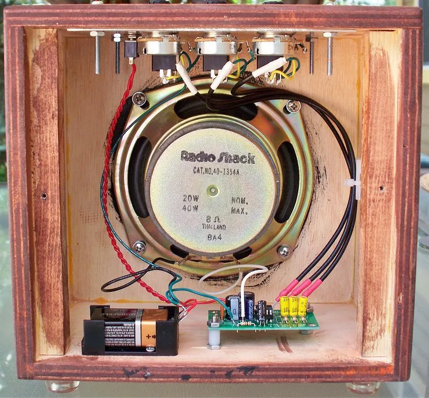
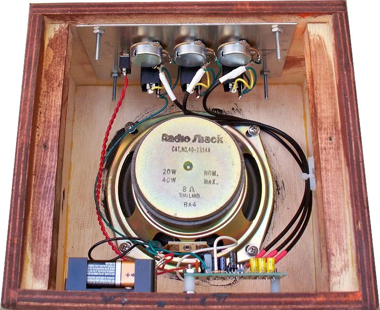
I built a small plywood box (from scrap lumber) to accomodate the speaker, battery holder and the plate holding the input jacks, level controls and power switch. I did not use an LED because I want the battery's energy capacity to go into making sound waves not photons. If you add an LED I would put a 1K current limiting resistor in series with it and make sure to wire it after the power switch.
The grill is made from powder coated decorative aluminium from Lowes. It comes in 2' x 2' sheets near the sheet metal products. Grill cloth would work fine as well.
Project Parts List (Rev 02)
All cap voltages should be 25V or more. All resistors are 1/4W 5% (1% will work fine). MFOS PC boards use dual inline IC packages and usually 5mm (0.2") cap lead spacing unless the board's legend obviously calls for larger or smaller.
| Qty. | Description | Value | Designators |
|---|---|---|---|
| 1 | LM386N-4 Low Voltage Audio Power Amp | LM386N-4 | U18 |
| 3 | Potentiometer Linear Taper | 100K | R1, R3, R7 |
| 1 | Resistor 1/4 Watt 5% | 10 ohm | R6 |
| 3 | Resistor 1/4 Watt 5% | 100K | R2, R4, R8 |
| 1 | Resistor 1/4 Watt 5% | 1K | R5 |
| 1 | Aluminum Electrolytic Capacitor | 10uF | C6 |
| 1 | Aluminum Electrolytic Capacitor | 220uF | C3 |
| 1 | Aluminum Electrolytic Capacitor | 470uF | C7 |
| 1 | Capacitor Aluminum Bipolar (non polarized) | 10uF | C9 |
| 3 | Capacitor Aluminum Bipolar (non polarized) | 1uF | C1, C4, C8 |
| 1 | Ceramic Capacitor | .047uF | C5 |
| 1 | Ceramic Capacitor | .1uF | C2 |
| 1 | Speaker 2 1/4 inch 8 ohm | 8 ohm | SPKR1 |
| 1 | Switch SPST | SPST | S1 |
| 3 | Jack 1/4" 2 Terminal | 1/4" jack | J1, J2, J3 |
| 1 | Battery | 9V Battery | B1 |
| 1 | 9V Battery Clip | ||
| 3 | Potentiometer Knobs |
Revision Zero Schematic & PC Board Information
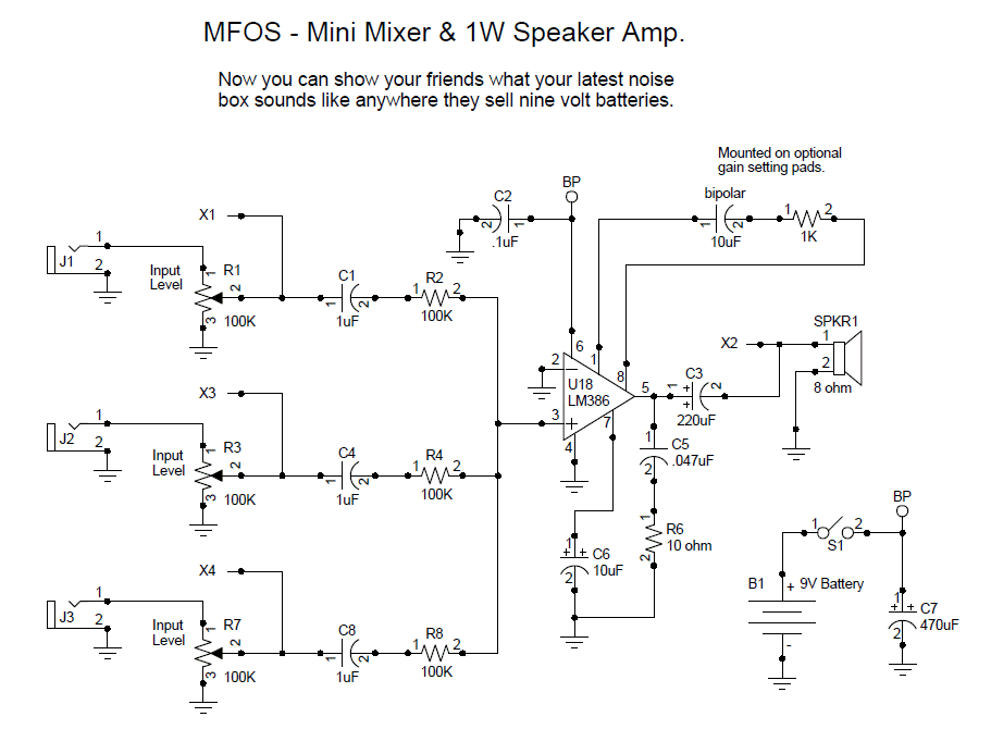
This project changed slightly and the current information is above. This information describes the original Rev 0 project and board. The new circuit makes first class citizens of the gain setting resistor and cap and eliminates a resistor that was no longer used.
Schematic
PC Board Information
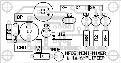
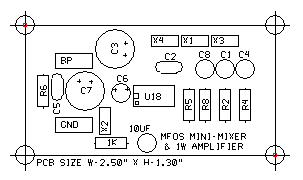
Parts Layout With Component Designators
When you are trouble shooting you'll need this view so that you can refer between the designators and the components shown in the schematic.
Notice that here we use the "optional" gain set pads to boost the amp's gain up to a bit over 50. That is what the 10uF bipolar (non-polarized) capacitor and the 1K resistor are for. There are no designators screened on the PCB for those two parts but they must be added. Making the gain set resistor lower will increase the overall gain. I would not go lower than 500 ohms or you will get distortion. Note that R5 is not used.
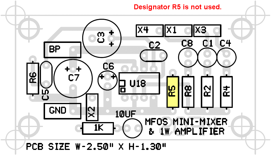
Parts Layout With Component Values
Print out this view to use when you are populating the PC board. Not having to continually refer between designators and the schematic will save you a lot of time.
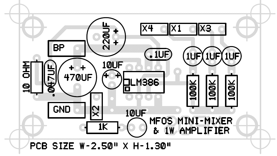
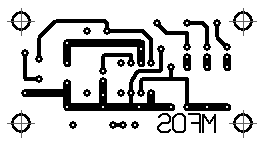
Top Copper
MFOS PCB Images are as viewed from the top of the PC Board. Keep that in mind when you are using the patterns with photo or copier processing.
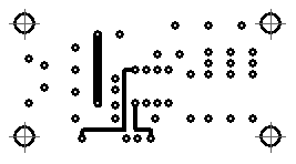
Bottom Copper
MFOS PCB Images are as viewed from the top of the PC Board. Keep that in mind when you are using the patterns with photo or copier processing.
Silk Screen
MFOS PCB Images are as viewed from the top of the PC Board. Keep that in mind when you are using the patterns with photo or copier processing.
Rev 0 Project Parts List
| Qty. | Description | Value | Designators |
|---|---|---|---|
| 1 | LM386N-4 Low Voltage Audio 1W Power Amp | LM386N-4 | U18 |
| 3 | Potentiometer Linear Taper | 100K | R1, R3, R7 |
| 1 | Resistor 1/4 Watt 5% | 10 ohm | R6 |
| 3 | Resistor 1/4 Watt 5% | 100K | R2, R4, R8 |
| 1 | Resistor 1/4 Watt 5% | 1K | Gain Set R |
| 1 | Aluminum Electrolytic Capacitor | 10uF | C6 |
| 1 | Aluminum Electrolytic Capacitor | 220uF | C3 |
| 1 | Aluminum Electrolytic Capacitor | 470uF | C7 |
| 1 | Capacitor Aluminum Bipolar (non polarized) | 10uF | Gain Set C |
| 3 | Capacitor Aluminum Bipolar (non polarized) | 1uF | C1, C4, C8 |
| 1 | Ceramic Capacitor | .047uF | C5 |
| 1 | Ceramic Capacitor | .1uF | C2 |
| 1 | Speaker (2" to 5") 8 ohm 1W or greater | 8 ohm 1W | SPKR1 |
| 1 | Switch SPST | SPST | S1 |
| 3 | Jack 1/4" 2 Terminal | 1/4" Phone Jack | J1, J2, J3 |
| 1 | Battery | 9V Battery | B1 |
| 1 | 9V Battery Clip | ||
| 3 | Potentiometer Knobs |
All work © Ray Wilson / Music From Outer Space - musicfromouterspace.com. The mini mixer, its circuit, text and images are Ray's.
Mirrored and recoded by Mess O' Pedals to preserve Ray's work and keep it accessible. Only the HTML is mine - the design, the words, and the wit are all Ray Wilson's.