Mood Plush
A squeeze-triggered CD4093 synth that gets worked up · By Onion Madder · Mess O' Pedals
Squeeze it and it chirps, and an eye flashes with the chirp. Squeeze it again and it chirps a little higher. Keep handling it and it climbs. Walk away and it drains back down to silent and dark over half a minute or so. The whole mood lives in one capacitor: every squeeze pours a little charge into it, a big resistor lets it leak away slowly, and the voltage on it drives the LED inside a home-made vactrol. That LED lowers a photocell's resistance, and the photocell sets the pitch - so the eye and the voice are literally the same signal.
Two chips doing two different jobs: a CD4093 supplies the input gate, the oscillator and the eye driver, and an NE555 sits between them as a one-shot so that a single squeeze registers as one squeeze and not six. It is built for a plush toy - the piezo goes in the stuffing, the eye goes where an eye goes, and the board, the speaker and a 9V battery ride inside - so everything you touch or see hangs off the board on wires. All of it fits on a 14 by 22 board.
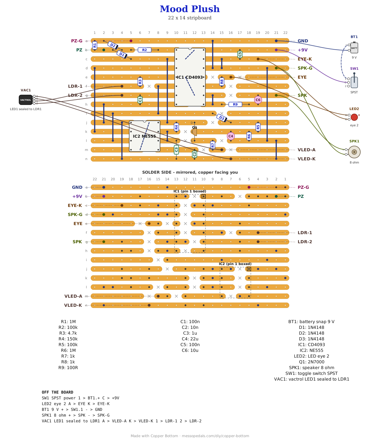
⚠ Before you start tap to expand / collapse
The clamp diodes are not optional. A hard whack on a piezo can put out tens of volts. D1 and D2 shunt that to the rails before it reaches the CD4093. Skip them and you will eventually kill the chip.
Five parts care which way around they go: C4 and C6 (the stripe marks the minus leg), the three diodes (the band is the cathode, and Copper Bottom draws which end it goes), plus the two LEDs off the board (the long leg is the anode).
The MOSFET's legs are Source, Gate, Drain, with the flat face toward you. Its gate is the one place in the circuit that draws nothing, which is the whole reason it is a MOSFET and not a transistor - see the troubleshooting table.
Make the vactrol first. LED1 and the photocell get taped or heat-shrunk face to face so no room light gets in, and the sealed lump arrives at the board as four wires.
What you'll need
tap to expand / collapse
Eighteen parts on the board plus the two chips, the MOSFET and fifteen links, and six off it.
- 1× CD4093 quad NAND Schmitt trigger, DIP-14 (IC1) - spot it: fourteen legs, 4093 in the part number, a notch at one end and a dot beside pin 1. Three of its four gates are used: input, oscillator, eye driver. Pin 11, the spare gate's output, is left empty on purpose
- 1× NE555 timer, DIP-8 (IC2) - spot it: eight legs, half the length of the 4093, NE555 or LM555 printed on top, half-moon notch at one end. Both chips solder straight to the board
- 1× 2N7000 N-channel MOSFET (Q1) - spot it: TO-92, three legs, one flat face, 2N7000 printed on the flat. Not a 2N3904 - it looks identical and it is the wrong part here, see troubleshooting
- 2× 1M resistor (R1, R6) - spot it: bands brown-black-green. One holds the piezo at ground, the other drains the mood
- 2× 100K resistor (R2, R5) - spot it: bands brown-black-yellow. One feeds the piezo into the chip, the other sets how much each squeeze adds
- 1× 150K resistor (R4) - spot it: bands brown-green-yellow on a 4-band part, brown-green-black-orange on a 5-band metal film. The one-shot's timing resistor
- 1× 4.7K resistor (R3) - spot it: bands yellow-violet-red. The fixed part of the oscillator's timing resistor; the photocell is the rest
- 2× 1K resistor (R7, R8) - spot it: bands brown-black-red. One in front of each LED
- 1× 100R resistor (R9) - spot it: bands brown-black-brown. Easy to mix up with the 1K - the third band is the difference. Speaker series resistor
- 2× 100nF ceramic (C1, C5) - spot it: disc printed 104. C1 sets the octave the whole thing lives in; C5 is supply decoupling. Either way around
- 1× 10nF ceramic (C2) - spot it: disc printed 103. Steadies the 555's control pin. Either way around
- 1× 1 µF film capacitor (C3) - spot it: a little box, printed 105, either way around. The one-shot's timing cap. An electrolytic works too, stripe toward the ground strip
- 1× 22 µF electrolytic (C4) - spot it: a small can with a stripe down one side. This is the mood. The stripe marks the minus leg and polarity matters
- 1× 10 µF electrolytic (C6) - spot it: a smaller can, same stripe. Speaker coupling, polarity matters
- 3× 1N4148 diode (D1, D2, D3) - spot it: tiny glass body, a black band at one end - the band is the cathode. Two of them are the clamp on the piezo, the third is the one-way valve into the mood cap. All three lie on the slant
- 15× wire links - offcuts of component leg. J1 and J15 run under IC1's body and J9 under IC2's, so they go in before the chips do
Off the board
- 1× piezo disc with leads (PZ1) - spot it: a brass disc with a white ceramic center and a red and a black wire. This is the thing you squeeze. Red to PZ, black to PZ-G
- The vactrol (VAC1 on the drawing): 1× LED (LED1) and 1× photocell (LDR1, GL5528 or similar), sealed face to face in black tape or heatshrink. The LED is buried, so nobody sees it - but pick a bright one, because the 1K in front of it only allows a few milliamps and the cell needs all the light it can get. LED long leg to VLED-A, short leg to VLED-K; the cell's legs to LDR-1 and LDR-2, either way around
- 1× LED, eye 2 (LED2) - spot it: the one people actually see, so pick the pretty one. Long leg to EYE, short leg to EYE-K
- 1× 8Ω speaker, small (SPK1) - spot it: any small speaker, to SPK and SPK-G. Expect it quiet; see Before you play
- 1× 9V battery and a snap. Red through the power switch to +9V, black to GND. A 555 and a 4093 are both happy anywhere from 5V to 15V, but the mood voltage has to climb past the MOSFET's threshold before the vactrol does anything, so a lower supply gives it less room to climb. Untested below 9V
- An SPST toggle for power, in the battery's red lead between the snap and the board's +9V pad. Every build on this shelf gets one, and the drawing above shows it
The layout file is the guide
Like every layout on this shelf, the build document for this one is the file itself: ↓ Download Mood_Plush.json - import it into Copper Bottom and the editor gives you the board picture, the placement walkthrough, the electrical checks and a printable build sheet, all from the same file. No coordinates are written out on this page on purpose: the editor is the viewer, and a number typed twice is a number that can drift.
J1, J15 and J9 run under the chips, so solder them before the chips go in. J1 joins IC1's two supply pins, 2 and 14, under its body; J15 carries the oscillator from IC1's pin 4 across to pin 9; J9 ties the 555's pin 4 to pin 8 under its body.
Copper Bottom reads this board clean: nothing shorted, nothing floating, and every connection in the netlist below is on the board. The one thing it mentions is IC1 pin 11, the spare gate's output, which is left empty.
The netlist
My script wrote this from the design and the board was checked against it in Copper Bottom: every connection it names is on the board and nothing on the board is missing from it. The same script checks every net against the breadboard version this guide replaces, hole by hole from my build sheet, both ways, so the two are one circuit. GATE is the one-shot's pulse, MOOD the voltage on the mood cap, OSC the voice and TIM and OSCIN the two ends of the photocell. The empty pin is not listed.
The off-board wiring
Twelve pads leave the board: the piezo, the vactrol, the eye, the speaker and the supply.
| Pad | Goes to |
|---|---|
| PZ / PZ-G | The piezo disc's red and black wires. PZ-G is ground |
| LDR-1 / LDR-2 | The vactrol's photocell, either way around. It is part of the oscillator's timing resistor |
| VLED-A / VLED-K | The vactrol's LED: long leg to VLED-A, short leg to VLED-K |
| EYE / EYE-K | Eye 2, the LED people see: long leg to EYE, short leg to EYE-K |
| SPK / SPK-G | The speaker, either way around |
| +9V / GND | The battery snap: red through the power toggle to +9V, black to GND |
Before you play
Supply off: check C4 and C6 have their stripes where the drawing puts them, the three diode bands point the way the drawing shows, and the MOSFET's flat face is the way Copper Bottom draws it. Meter PZ to GND: about 1M, the piezo's pull-down. Anything near zero is a short. Then switch on: nothing should light and nothing should make a noise. Tap the piezo.
Nobody has built this yet, so this is what the circuit says should happen. The vactrol's LED does not light until the mood voltage on C4 climbs past the MOSFET's threshold, a couple of volts, and each squeeze adds well under a volt. So expect the first few taps to come out low and clicky rather than as a chirp - the cell is still dark and the oscillator is running at a few hertz. Keep tapping and it should wake up and climb, with the eye flashing in time. Stop, and over half a minute or so it settles back to silence.
Expect it quiet. The speaker hangs straight off a CD4093 output through 100R, and a 4093 can only push a few milliamps. It will make a noise, but not a loud one. An LM386 stage between the SPK pad and the speaker is the fix, not a fault.
If it doesn't work
| Symptom | Check |
|---|---|
| Nothing at all, dead silent, no flash. | Meter IC1 pin 14 and IC2 pin 8 to ground: both should read the battery. Then the cuts, every one, against the solder-side drawing, and look for a bridge of solder between strips. |
| Constant tone, never stops. | The 555's output is stuck high. Check R4 and C3, and that pin 4 reads the battery. |
| One squeeze gives a burst of chirps. | The one-shot is too short for the piezo's ringing. Raise R4 or C3. |
| Nothing at all on tap. | Probe IC1 pin 3 while tapping. No pulse there means the piezo network - check D1 and D2 point the right way and the piezo's red wire is on PZ. |
| Chirps but the pitch never changes. | Vactrol light leak, or C4 never charging. Cover the LED and cell pair properly, then meter C4's plus leg as you tap: the voltage should build a little on each squeeze. If it does not, check D3's band. |
| Chirps but very quietly. | Expected - a bare CD4093 output into a speaker. See Before you play. |
| The first several taps are clicks, not chirps. | Also expected, if the circuit does what it says: the cell is dark until the mood climbs past the MOSFET's threshold. Keep tapping. If it never climbs, see the row above. |
| The vactrol's LED glows at rest, or the pitch sits high with nobody touching it. | Q1 leaking or C4 not draining. Confirm R6 is 1M (brown-black-green, not brown-black-yellow). |
| The mood decays too fast. | The MOSFET's gate should draw nothing. If you substituted a 2N3904, its base current is draining C4 - that is the trade. Raise R6, or go back to a MOSFET. |
| Pitch swings but it sounds bad. | Good. |
How it works, in one breath
The piezo makes a spike when you squeeze it. Two diodes keep that spike inside the rails, a Schmitt gate cleans it into one hard edge, and a 555 wired as a one-shot stretches that edge into a pulse about 165 ms long - so one squeeze is one event, however much the disc rings. That pulse does two things at once. It enables the oscillator, the second 4093 gate, for as long as it lasts, which is the chirp. And it pours a little charge through a diode and a 100K into C4, the mood cap, which a 1M drains back toward ground at its own pace - about twenty seconds to lose most of what it had. The voltage on C4 sits on the gate of a MOSFET, which draws nothing from it, and the MOSFET pushes current through the LED sealed against the photocell. More mood, brighter LED, lower cell, higher pitch. The third gate just inverts the oscillator's output to flash the visible eye in time with the voice.
Things to try
None of these have been tried either - they are the obvious knobs on the design, and every one is a single part.
- Swap C1 (100nF) for 10nF and the whole voice jumps up an octave or so.
- A pot in series with R6 and you can dial how long it stays worked up.
- Replace R5 with a pot to change how much each squeeze adds. Low, and one squeeze maxes it out, which is a very different animal.
- A second cell across LDR1 - on the LDR-1 and LDR-2 wires - poking out through the fur, and it reacts to light as well as touch. That is the Chubbles trick.
- Use the spare gate. Gate 4 is sitting there with its inputs grounded. Wire it as a slow oscillator and mix it into the timing node for a wobble that gets faster as it gets more agitated.
- Give it a voice. An LM386 Hornet stage between the SPK pad and the speaker, and it stops whispering.
This one is an original: a piezo, a 4093 and a 555 arranged so the eye and the voice are the same voltage. Nobody has built it yet, me included - when I have, this line will say so. Build it, bend it, make it yours.