Optical Tremolo
A 555, a transistor and a homemade vactrol turning the volume up and down for you · By Onion Madder · Mess O' Pedals
Tremolo is a volume knob being turned back and forth, and this box does it with light. A 555 wobbles slowly, a 2N7000 turns that wobble into LED brightness, and the LED is taped to a photocell that sits across the signal - the same homemade vactrol as the Opto Duet, doing a more respectable job. The cell pulls the signal toward ground when the light is on, so the volume dips in time. Rate knob, depth knob, an LED blinking the beat, 3.5 mm in and out. It is an upright box for the synths, not a pedal, so there is no footswitch.
What you'll need
tap to expand / collapse
- 1× NE555 timer, 8-pin DIP - spot it: 555 in the part number, notch or dot marks pin 1
- 1× 2N7000 MOSFET, TO-92 - spot it: 2N7000 on the flat face; legs are S, G, D left to right with the flat toward you. Not a 2N3904 - see why below
- 1× 1N5817 Schottky - spot it: black body, silver band. Reverse-polarity protection; a 1N4001 works and costs half a volt
- 3× 10K (brown-black-orange) - the clock's upper timing resistor, the rate pot's floor, and the series half of the signal divider
- 1× 2K2 (red-red-red) for the rate LED, 1× 470R (yellow-violet-brown) for the vactrol LED, 1× 1M (brown-black-green) holding the output at ground
- 1× 4.7 µF electrolytic - the LFO's timing cap. Spot it: the stripe marks the negative leg. Bigger is slower
- 1× 100 µF electrolytic across the supply
- 2× 1 µF ceramic (105) - the coupling caps in and out. Film is fine too
- 1× 100n ceramic (104) on the 555's control pin
- 1× stripboard, 14 strips × 30 holes or larger, and wire for eight links
Off the board
- 1× 500K linear pot (B500K) - the rate. Two lugs
- 1× 10K linear pot (B10K) - the depth. Two lugs
- 1× bright LED and 1× photocell (LDR), sealed together face to face with heat-shrink or black tape - the vactrol. A red or white LED and any cell that reads under a few K in bright light
- 1× LED for the panel, any color - it blinks the rate
- 2× 3.5 mm jacks - in and out
- 1× 9V battery snap or a DC jack, and a toggle for power
- An upright 125B - the drill template further down
The layout file is the guide
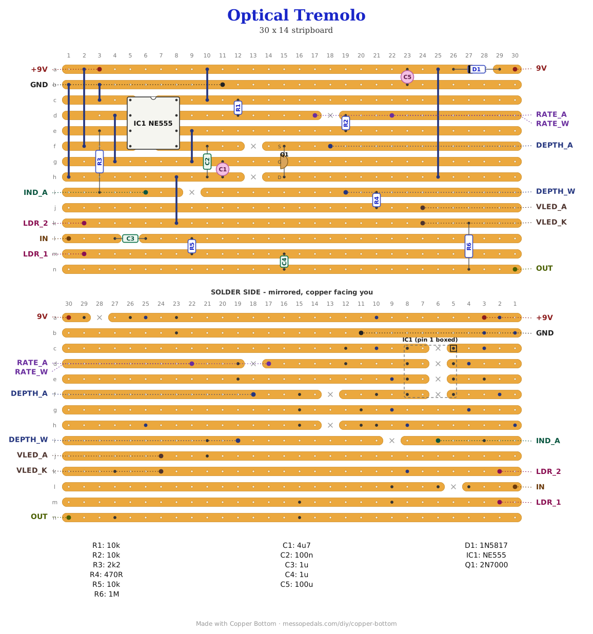
Like the 555 theremin and the Opto Duet, the build document for this one is the file itself: ↓ Download Optical_Tremolo.json - import it into Copper Bottom and the editor gives you the board picture, the placement walkthrough, the electrical checks and a printable build sheet, all from the same file. No coordinates are written out on this page on purpose: the editor is the viewer, and a number typed twice is a number that can drift.
The netlist
Quoted verbatim from the layout file. It was written from the board, so checking the board against it can only pass - what it is for is carrying the circuit somewhere else, and telling you what each strip is supposed to be doing while you stare at it.
The off-board wiring
Fourteen pads leave the board. The vactrol is the only part that needs building first.
| Pad | Goes to |
|---|---|
| 9V / GND | The supply, 9V, through the power toggle. GND also takes both jack sleeves and the rate LED's cathode |
| IN / OUT | Jack tips. Sleeves to GND |
| RATE_A / RATE_W | The rate pot: one outer lug and the wiper. Tie the unused lug to the wiper |
| DEPTH_A / DEPTH_W | The depth pot, the same way. Fully on the pad side is the deepest |
| IND_A | The panel LED's anode. Cathode to GND. It blinks at the rate |
| VLED_A / VLED_K | The vactrol's LED, anode and cathode. Build the vactrol first: LED and cell nose to nose, then heat-shrink or black tape over the pair so no room light reaches the cell |
| LDR_1 / LDR_2 | The vactrol's cell, either way round - a photocell has no polarity. LDR_2 is ground |
| +9V | Nothing. A test point on the protected rail, and it tells Copper Bottom's checker that strip is a supply |
The vactrol has to be dark. The cell is the volume control, and every bit of room light that reaches it is volume the LED cannot take away. If the tremolo is shallow no matter where the depth knob sits, that is the first thing to check - then the LED's polarity, since a backwards LED is a vactrol that never lights.
How it works, in one breath
The 555 runs as an astable at tremolo speeds: 10K up top, the rate pot plus a 10K floor in the middle, 4.7 µF to ground, which is roughly a third of a cycle a second to ten a second. Its square output goes nowhere but the panel LED. The wave that matters is on the timing capacitor: the chip charges it to two thirds of the rail and lets it fall to one third, over and over, which is a triangle, and a triangle turned into brightness is a smooth swell instead of a chop.
You cannot hang an LED on that capacitor - the current would pull the timing off. The 2N7000 is a source follower: its gate draws nothing, its source copies the gate voltage less a couple of volts, and from there the depth pot and a 470R set how hard the vactrol LED is driven. At the bottom of the triangle the source sits below the LED's forward voltage and it goes out; at the top it is a few milliamps bright. That off-to-bright swing is why it is a MOSFET and not a 2N3904: a bipolar's base would load the cap.
The signal comes in through a 1 µF, through a 10K, and out through another 1 µF, with the cell from the middle node to ground. Dark, the cell is hundreds of K and the signal passes untouched. Lit, it drops to a few K and the 10K against it is a divider, twenty-odd dB down. Depth is how bright the LED gets; rate is the 555. A 1M on the output keeps the jack quiet when nothing is plugged in.
Two numbers a bench will settle, unmeasured. How deep it goes depends on your cell and how well the vactrol is sealed - a cell that bottoms out at 1K gives more than one that stops at 5K, and the 10K series resistor is the other half of that ratio, so raise it for more depth at the cost of a little level. And the follower's output swing depends on the 2N7000's threshold, which varies part to part; if the LED never quite goes out, a 1K in series with the 470R fixes it. Built for line-level synths: a guitar into a 10K is loaded harder than it would like.
Print at 100% / “Actual size”, never “Fit to page” - check the bar measures exactly 4″ before you touch a drill. The face is 66 by 121 mm but only 42 mm of it is drillable once the lid lip is clear.
Nobody has drilled this one yet. The hole sizes come from the parts; where they sit is this format applied to them. Offer the sheet up to the box and check it against your own parts before you make a hole.
Circuit from the NE555 datasheet's astable, a source follower off its timing pin, and the shunt vactrol every optical tremolo since the sixties has used. The vactrol is the Opto Duet's; the layout and the box are Onion Madder's, drawn in Copper Bottom.