Opto Duet
Two 555 theremins that play each other, on one stripboard · By Onion Madder · Mess O' Pedals
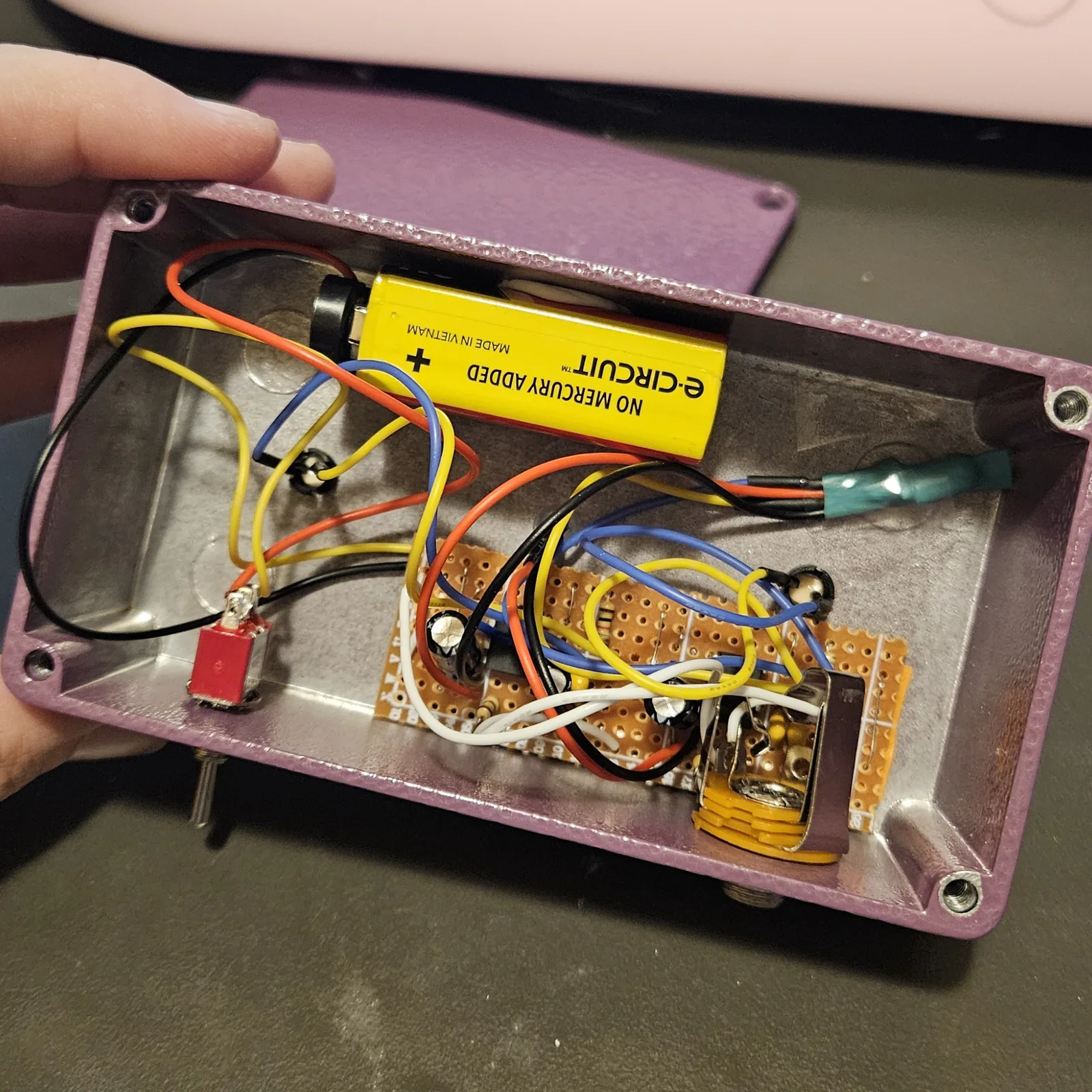
I was inspired to create this after building two of my 555 theremins and wiring their LDRs against each other to see what would happen. This layout combines two copies on a single board that easily fits inside a 125B enclosure, with room for a 9V battery if you prefer it. although the circuit wants at least 6v to run properly. Using a battery over time will leave you with a pile of half-dead cells. This build takes approximately 45 minutes.
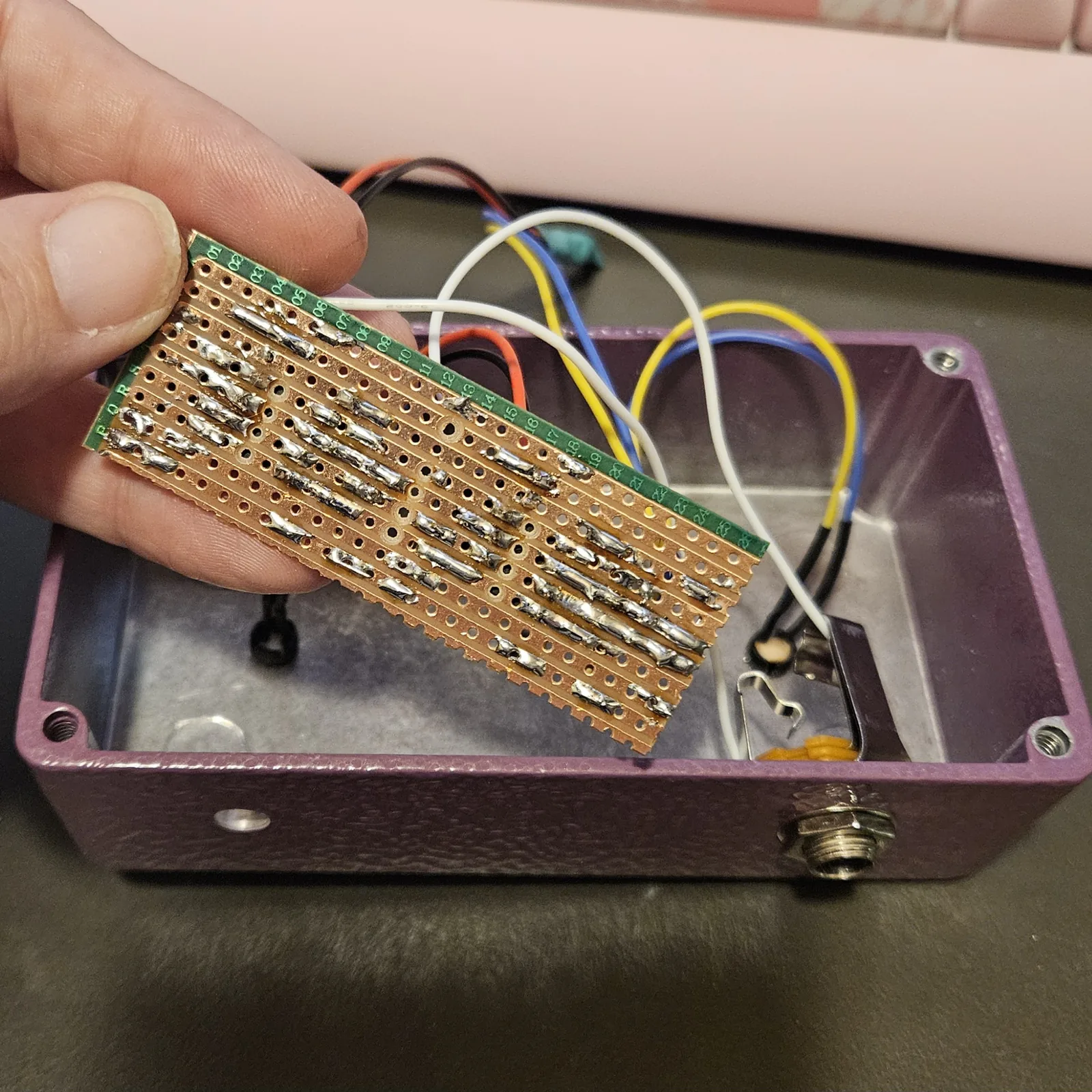
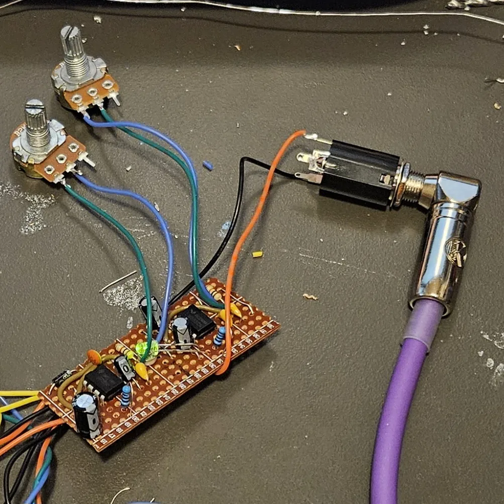
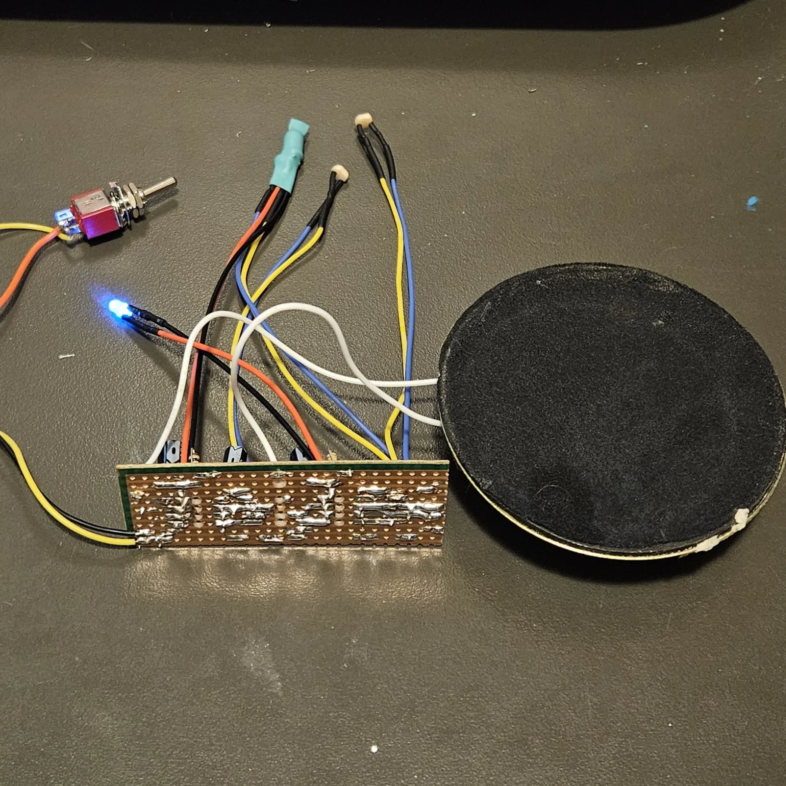
It is built and it works. The first attempt died at 90% when a copper strip lifted off a cheap board mid-solder. The second went together on the same cheap board with the iron turned down, and it came up on the first power-up: it sings from a center-negative 12V DC wall wart. The second build died when I accidentally plugged it into a center-positive supply, which is why I added the rectifier diode, D1 on the board now. The third build is up and running: third time really is the charm.
What you'll need
tap to expand / collapse
- 2× NE555 timer, 8-pin DIP - spot it: NE555 printed on top, notch marks pin 1
- 1× stripboard, 9 strips × 23 holes or larger - a cheap board is fine, but turn your iron down.
- 2× 1K resistor (brown-black-red) - one per timing chain
- 2× 100R resistor (brown-black-brown) - the output resistors
- 1× 10µF electrolytic - the engine's timing cap, the part that turns a scream into a tick.
- 3× 100n ceramic (printed 104) - the voice's timing cap, and C8 and C9, one across the supply beside each 555
- 2× 10n ceramic (printed 103) - control-pin decoupling, one each
- 3× 100µF electrolytic - two output couplers, one across the rails
- 1× 1N5817 Schottky (D1) - spot it: black body, gray band. On the board, in the +12V lead, band toward the chips. Keeps your board from getting fried like mine
Off the board
- 3× photocell (LDR) - the wiggly-line disc. Same type as the theremin guides. Any will work, but which three you grab sets how the finished box sounds
- 2× LED, any color - both run bare, no resistor.
- 1× small speaker and a power supply - a 12V DC wall wart, center-negative. A 555 chip will run from 4.5V, but this box wants 6V and up: below that the LEDs stop flashing, because they light off the swing through the coupling caps. A fresh 9V battery runs it; a tired one takes the LEDs out first and looks exactly like a broken build.
- Heat-shrink big enough to swallow the LED and one photocell face to face - that is the whole vactrol
- 1× - a toggle switch for the positive supply leg, so the box has an off.
- 1× DC jack, center-negative to match the wall wart
The layout file is the guide
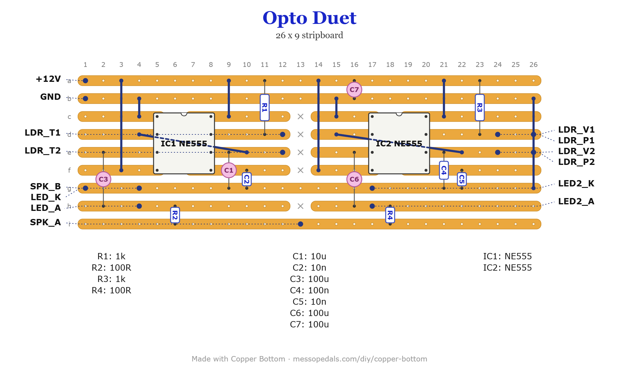
Like the 555 theremin layout, the build document for this one is the file itself: ↓ Download Opto_Duet.json - import it into Copper Bottom and the editor gives you the board picture, the placement walkthrough, the electrical checks and a printable build sheet.
There is also a one-chip version on an NE556 - the same circuit redrawn, checked in Copper Bottom and not yet built.
The off-board wiring
Fourteen pads leave the board. Everything with a face goes where its job says:
| Pad | Goes to |
|---|---|
| +12V / GND | The supply, one for both oscillators. Mine is a 12V DC wall wart, center-negative. The positive leg goes through an on/off toggle to the +12V pad; D1 on the board takes it from there. A 9V battery snap works too |
| VCC | Nothing. A test point on the protected side of D1, and it tells Copper Bottom's checker that strip is a supply |
| SPK_A / SPK_B | Speaker hot / return. Both boards mix at SPK_A through their own 100Rs - no extra mixing resistors, see below |
| LED2_A / LED2_K | The indicator. Same wiring as the first LED but on the voice's half - across the strip between C6 and R4, cathode to the ground rail - so it flashes with the voice. Nothing is sealed against this one; it is there to be looked at |
| LED_A / LED_K | The bare LED - anode to LED_A, cathode to LED_K. It seals face to face with the vactrol cell inside heat-shrink |
| LDR_V1 / LDR_P1 LDR_V2 / LDR_P2 | Four pads, two nodes. LDR_V1 and LDR_P1 are the same strip; so are LDR_V2 and LDR_P2. Two photocells bridge those two nodes, which is what puts them in parallel: the vactrol cell, sealed in heat-shrink with the LED, and the pitch eye, facing out of the box for room light and your hands. Take any upper pad and any lower pad for each cell - on my board the vactrol sits on LDR_V1 and the pitch eye on LDR_V2 |
| LDR_T1 / LDR_T2 | The tempo eye, one cell across the engine's two timing strips. It faces out of the box too: room light and your hands set the tick rate |
D1 is the whole of the reverse-polarity protection. It sits on the top strip across a cut, between the +12V pad and everything else, so a backwards plug meets a reverse-biased diode and nothing on the board sees it. C8 and C9 beside the two chips keep each 555's supply quiet. A Schottky is the part to use for D1 rather than a 1N400x: it drops about 0.3V instead of 0.7V, and this box already wants at least 6V.
That pad doubling is the parallel wiring, and parallel is load-bearing: the lit cell wins, so each engine flash yanks the pitch up and releases it. In series they would politely average and the chirp would die. It also means the pad names are a convenience, not an assignment - nothing electrical changes if your vactrol lands on the pads labeled for the pitch eye.
The three cells you grab will change how this thing sounds, and that is not a
fault. A photocell is barely a spec: the common 5mm types look identical in the
bin and run roughly ten to one apart in resistance, and in a 555 the cell
is the timing resistor. So two boxes off the same pile genuinely are two different
instruments. The tempo eye sets how fast the engine ticks. The vactrol cell
and the pitch eye set how hard each flash yanks the voice - they are in
parallel, so what matters is the ratio between them rather than either one
alone. And a cell's recovery from light is slow and varies, which is roughly the
difference between a click and a chirp. Mine click, warble or chirp from build to build for
exactly this reason. Which of the three causes dominates is a read of the circuit, not
something I have measured.
If yours sounds wrong rather than merely different, swap the two
voice cells for each other before deciding one is bad - they are the same two nodes, so it
costs nothing to try. Past that, a meter sorts a pile fast: read each cell in room light,
under your thumb, and under a phone torch. Then uncover it and watch how long the number
takes to climb back. That last reading is the click-versus-chirp one, and it is the one
nobody ever takes.
The trick: the LED lives behind the cap
This is the discovery the whole box turns on, found by moving one bare LED strip by strip until the loop came alive. Put the LED on the engine's output strip and it just glows steady - twice over. Bare, it clamps the output at its own ~2V forward drop; and even resistored, a DC-coupled LED reports a level, and a feedback loop fed on a level finds a comfortable equilibrium and parks there.
Move it to the far side of the 100µF output cap - the strip between the coupling cap and the output resistor - and both problems vanish at once. The cap limits what a bare LED can draw, and a cap only conducts while the voltage moves, so on that strip the LED reports change. A loop fed on change has no resting point: if it ever sits still the LED starves, the photocell drifts, and the sitting-still is over. It has to hunt forever, at the tempo of the photocell's slow memory. That is why every classic opto-feedback synth AC-couples its lamp driver - and why this one was rediscovered at a bench with a lifted eyebrow instead of a datasheet.
If the LEDs fade, dim, or come back after a rest and then die again, look at your supply before you look at the board. They flash off the swing through the coupling cap, that swing tracks the rail, and the ultraviolet LEDs in mine want about 3.2 to 3.4V of it before they light at all - more than a red or a green would - while the 555s keep oscillating happily down to 4.5V. So the LEDs go dark first and the box carries on making noise, which reads as a wiring fault and is not one. Mine did exactly this on a dying 9V battery: rest it, it works for a minute, then fades. Back on the 12V wall wart it is fine.
Boxing it up
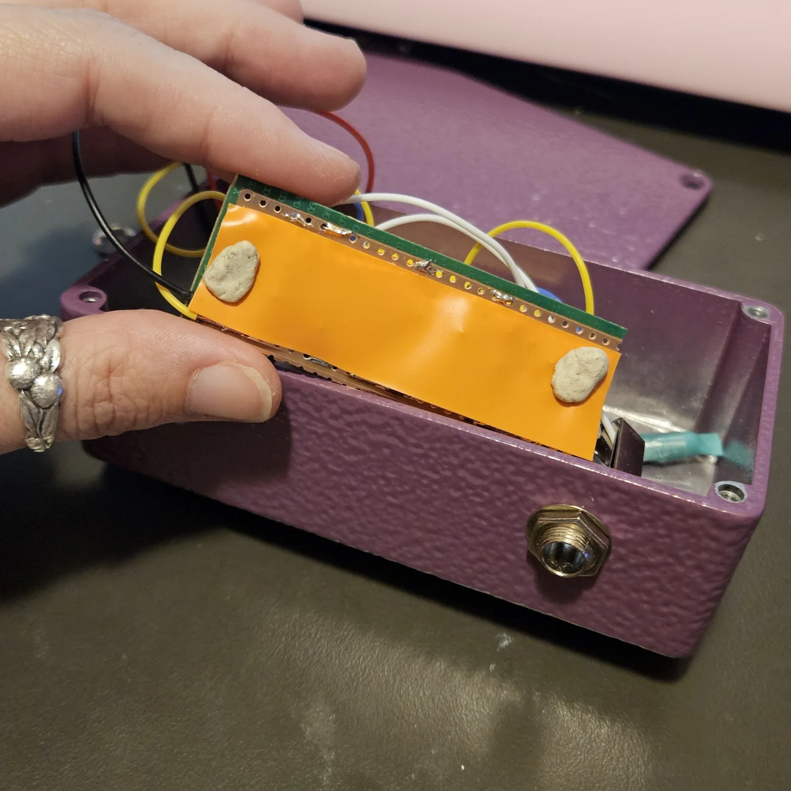
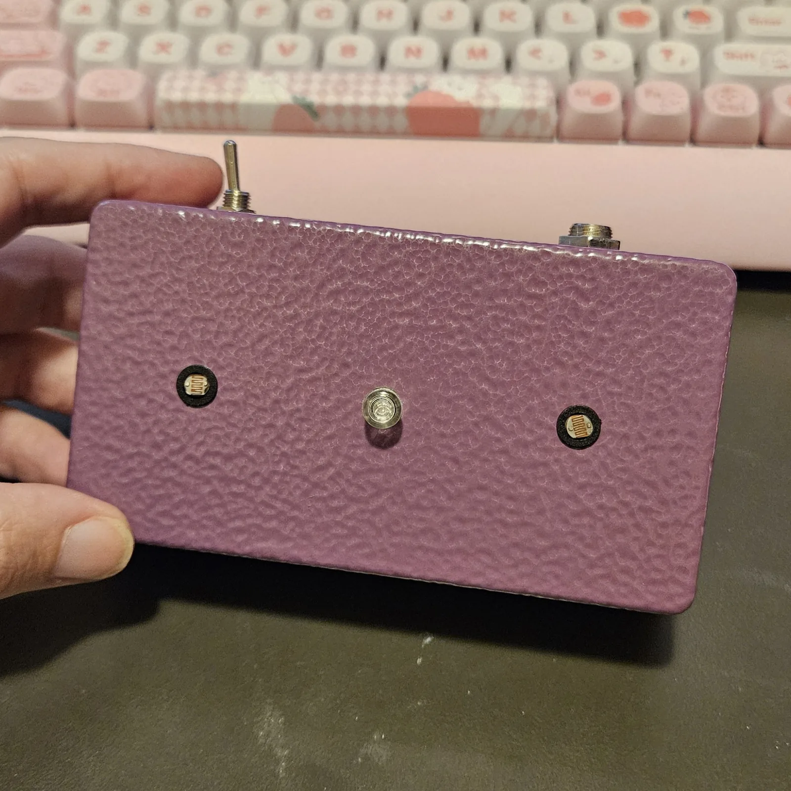
Mine lives in a 125B, horizontal: the two eyes and the indicator LED on the face, the power switch and a 1/4" output jack on the top edge. The two speaker pads feed that jack instead of a speaker - tip to SPK_A, sleeve to SPK_B - so the box plays through an amp.
Six holes, and none of them are fussy: 5 mm for each photocell and for the LED, 6.5 mm (1/4") for the toggle bushing, 9.5 mm (3/8") for the jack, and 8 mm if you want a barrel jack for the supply rather than passing the wall wart lead through a grommet. Wire that barrel jack center-negative. Keep every hole at least 12 mm in from an edge: the corner bosses and the lid lip live in there.
Check the plug before you power it, every single time. Pedal supplies are center-negative; most generic wall warts sold for everything else are center-positive, and they fit the same barrel jack perfectly. Backwards, the supply would go straight through both 555s and reverse-bias every electrolytic on the board. I swapped to a center-positive plug without looking and killed a working board with it, which is exactly what the 1N5817 in the positive leg is there to stop. With it in, a backwards plug does nothing at all - so if the box has gone silent right after you changed supplies, check the plug before you check your solder.

↓ Horizontal 125B (PDF)
The box lying down, as in the photos above. Eyes and LED on the face; switch, DC and output on the top edge. Landscape sheet, because a horizontal 125B unfolds wider than a portrait page can print. The DC hole is dashed because it is optional.
↓ Vertical 125B (PDF)
The box stood up, as in the demo video, with everything on the face - I/O along the bottom, controls above. Portrait sheet, for the same reason in reverse. The face is only 42 mm wide once the lid lip is clear, so the three eyes share one row.
↓ Vertical 125B, jacks on top (PDF)
The same upright box with the DC and the output moved to the top wall, so the cables leave upward; the eyes, LED and switch stay where the sheet above puts them. Two ways to drill one box; pick one.
Print at 100% / “Actual size”, never “Fit to page” - check the bar measures exactly 4″ before you touch a drill.
Things to try
- Retune the engine. The 10µF sets the tick rate - 4.7µF doubles the tempo, 22µF halves it. Same move as retuning a Hive voice.
- Retune the voice. Its 100n is the stock theremin value; the breadboard guide's cap-swap logic applies unchanged.
- If an LED ever dies young on the coupling node, ~100R inline should tame the edge pulses without killing the effect - untested, call it an experiment.
- Aim the eyes. Both outside cells respond to angle as much as light - mounting them as a creature's eyes is not just decoration, it is the interface.
- Add a jack. Line the bus out to an amp - and then bring the Hive's 10Ks back, because at that point they are correct again.
The 555 astable core is the same public circuit as my 555 Optical Theremin guides. The opto-coupled engine-and-voice arrangement - the LED behind the cap, the vactrol-plus-eye parallel pair, the chirp - is my own, found at the bench in August 2026. The layout, the file, and the words are mine. Build it, bend it, make it yours.