Police Lights
A red and blue wig-wag · One 555 on nine strips · By Onion Madder · Mess O' Pedals
One 555 timer, a red LED and a blue one, taking turns about three times a second. There is no second chip and no transistor: the red LED hangs from the timer's output down to ground, the blue one from the supply down to the output, so the output lights red when it goes high and blue when it goes low. They can never be on together. Ten parts on a 9 by 13 board, and a power switch in the supply lead.
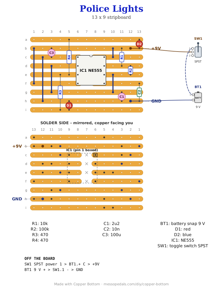
What you'll need
tap to expand / collapse
- 1× NE555 timer, 8-pin DIP (IC1) - spot it: NE555 or just 555 on top, a notch or a dot at pin 1. A CMOS 7555 or TLC555 sits in the same holes and works too
- 1× red LED (D1) and 1× blue LED (D2) - spot it: the long leg is the anode; the short leg, on the flat side of the rim, is the cathode, which the drawing marks. Plain LEDs, not self-flashing ones: those run their own clocks and drift out of step instead of taking turns. Pre-wired LEDs on leads work too, soldered into the same two holes, if the lights are going on a box away from the board
- 1× 10K resistor (R1) - spot it: bands brown-black-orange
- 1× 100K resistor (R2) - spot it: brown-black-yellow. With C1 it sets the rate
- 2× 470 ohm resistor (R3, R4) - spot it: yellow-violet-brown. One for each LED
- 1× 2.2 µF electrolytic (C1) - spot it: a small can with a stripe down the negative side. The timing cap
- 1× 100 µF electrolytic (C3) - the bigger can, across the supply
- 1× 10n ceramic (C2) - spot it: 103. On the control pin, to keep the rate steady
- Stripboard, 9 strips × 13 holes or larger, and solid wire for five links
Off the board
- 1× SPST toggle, the power switch, in the positive lead between the supply and the +9V pad
- 1× 9V battery and snap - spot it: red lead plus, black lead minus
The layout file is the guide
Like the rest of the stripboard shelf, the build document for this one is the file itself: ↓ Download Police_Lights.json - import it into Copper Bottom and the editor gives you the board picture, the placement walkthrough, the electrical checks and a printable build sheet, all from the same file. No coordinates are written out on this page on purpose: the editor is the viewer, and a number typed twice is a number that can drift.
The netlist
Quoted verbatim from the layout file. It says what each strip is supposed to be doing while you stare at it, and it carries the circuit somewhere else if you want to lay it out your own way.
The off-board wiring
Two pads leave the board.
| Pad | Goes to |
|---|---|
| +9V | The power switch; the switch's other side to the battery snap's red lead |
| GND | The battery snap's black lead |
Built, and seen
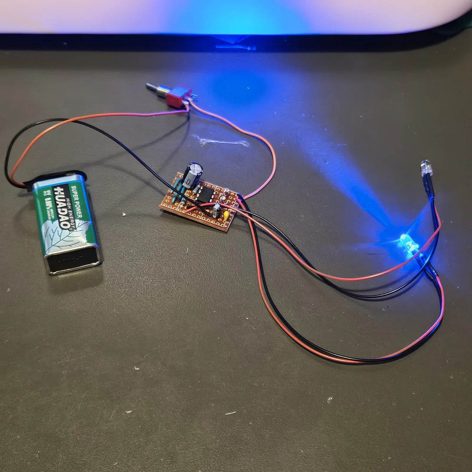
Built on the bench in October 2026, straight off the file above, running from a 9V battery through a toggle switch, and it looks like police lights.
How it works, in one breath
The 555 is wired as the datasheet's astable: C1 charges through R1 and R2 and discharges through R2, and the output flips each time. That works out at about 3.1 cycles a second, red for about 0.17 of a second and blue for about 0.15. When the output is high, current runs out of pin 3, through R3 and the red LED to ground. When it is low, current runs from the supply through the blue LED and R4 into pin 3. While red is lit, the blue LED has only the gap between the output and the supply across it, about 1.7 volts on an NE555, which is short of what a blue LED needs to light. By the arithmetic, each LED gets roughly 10 to 12 mA.
Things to try
- Slower or faster. A bigger C1 slows it down and a smaller one speeds it up: 4.7 µF is about one and a half flips a second
- A speed knob. A 100K pot in series with R2, wired as a variable resistor
- Brighter. R3 and R4 down to 330 ohms
- Other colors. Untested: a low-voltage LED such as a second red in the blue position may glow faintly while the other one is lit, because an NE555's high sits about 1.7 volts under the supply. A 7555 or TLC555 goes all the way up and should keep it dark
The circuit is the 555 astable from the datasheet, with one LED sourced and one sunk from the same output. The layout is Onion Madder's, drawn in Copper Bottom.