555 Theremin on Stripboard
The permanent home, drawn in Copper Bottom · By Onion Madder · Mess O' Pedals
The first layout in the stripboard series, and proof of the whole idea: the 555 theremin soldered onto a 9×18 scrap of stripboard, from a layout drawn and checked in Copper Bottom and then built exactly as drawn. One 555, one photocell, a speaker, and a board small enough to live inside almost anything. It worked on the first power-up - which is the editor's job, not luck.
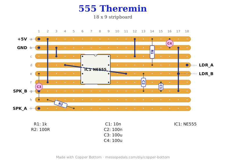
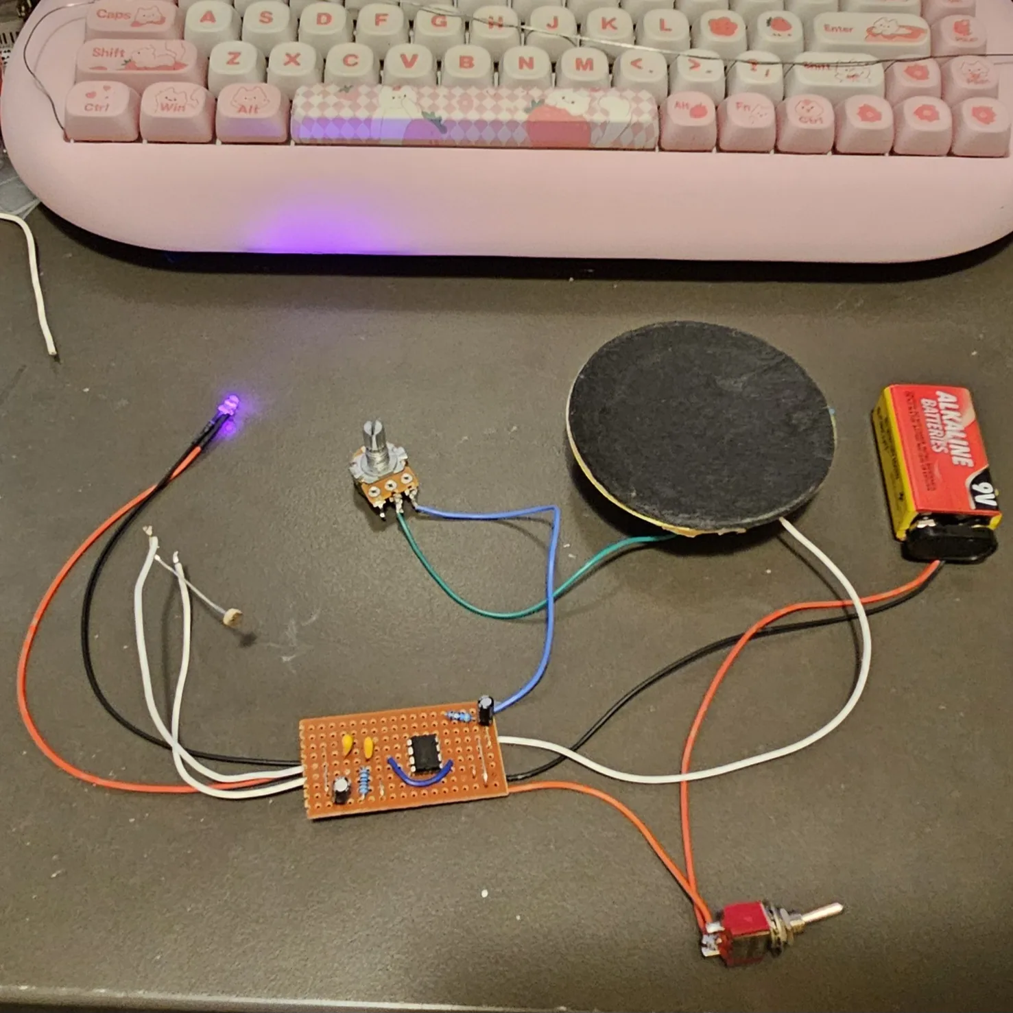
This page works differently from the breadboard guides. There is no numbered step list here, because the layout file is the build document: download it, import it into Copper Bottom, and the editor gives you the picture, a part-by-part walkthrough, its electrical checks, and a printable build sheet - always in agreement with each other, because they all come from the same file. What this page holds is the parts list, the netlist the board was verified against, and the off-board wiring.
⚠ Before you start tap to expand / collapse
This one is soldered. A hot iron holds about 350°C at the tip: work with ventilation, park the iron in a stand, and wash your hands after handling solder. Nothing electrical here can hurt you - the supply is a battery's worth of volts.
Polarity, twice: the two electrolytics each have a stripe marking the minus leg, and the chip's notch and dot mark pin 1. On stripboard a backwards part is a desolder, not a two-second fix - the walkthrough in the editor calls out the orientation as you go.
Check the cuts before the parts go in. All four track cuts sit in one column under the chip; a missed cut shorts the timer's opposite pins together. Meter each cut for no-continuity before you solder the chip down.
What you'll need
tap to expand / collapse
Eleven parts and a chip. The editor's build sheet lists them too - this version adds how to spot each one.
- 1× NE555 timer, DIP-8 - spot it: 555 in the part number, a notch at one end and a dot beside pin 1
- 1× 1K resistor - spot it: bands brown-black-red
- 1× 100 Ω resistor - the speaker's series resistor. Spot it: bands brown-black-brown
- 1× 10nF ceramic - the control-pin cap. Spot it: printed 103
- 1× 100nF ceramic - the timing cap. Spot it: printed 104
- 2× 100 µF electrolytics - output coupling and supply smoothing. Spot them: little cans; the stripe marks the minus leg
- 1× stripboard, 9 strips × 18 holes - cut a bigger board down; score and snap along a hole line
- 5× link wires plus hookup wire for the six off-board pads
Off the board
- 1× photocell (LDR) - the instrument itself, on flying leads so it can sit wherever your hand plays best
- 1× small speaker - anything from a salvaged toy upward
- Power: the pads are annotated for a 5V power module, and the bench build in the photo ran from a 9V battery - a 555 is happy anywhere from 4.5 to 16V, and the pitch range just shifts with the supply
- An SPST toggle for power, in the positive supply lead between the DC jack or battery and the board's supply pad. Not in the layout file - it is off the board, and every build on this shelf gets one
The layout file is the guide
↓ Download 555_Theremin.json - then open Copper Bottom and import it. The board is 9 strips of 18 holes, with 4 track cuts (all in one column under the chip - the editor placed them itself when the chip went down), 5 links, and 11 parts. The editor's walkthrough lays the parts in sensible order, its checks compare the copper against the netlist below, and its build sheet prints the whole thing for the bench.
This exact file is what I built from, and the build worked on the first try - so the file, the editor, and the board in the photo agree with each other. That is the point of the series.
The netlist - what the board was verified against
Straight out of the layout file. Every connection on the copper, written as nets; the
@ names are the off-board pads.
The off-board wiring
Six pads leave the board on flying leads. This is the part the editor cannot see, so it gets its own table.
| Pad | Goes to |
|---|---|
| +5V | Supply positive - the power module's + at 5V, or a battery's + lead |
| GND | Supply negative, shared with the speaker return |
| LDR_A | Photocell, one leg (the pin-7 end of the timing network) |
| LDR_B | Photocell, other leg (the pin-6 end) |
| SPK_A | Speaker, hot leg |
| SPK_B | Speaker, return leg - it shares the ground net |
The photocell has no polarity - either leg to either pad. The speaker doesn't care either. That means the only off-board mistakes possible are the two supply leads, which is a comfortable place for a first soldering project to be. A power switch, an indicator LED or a volume pot can ride along off-board too, like on my bench build - none of them are part of the layout.
How it works, in one breath
It is the same 555 astable as the breadboard theremin, shrunk to its essentials: the chip charges the timing cap through the 1K and the photocell, so the amount of light falling on the cell is the pitch - wave a hand and the note follows your shadow. The output pin drives the speaker through the coupling cap and the 100 Ω, and the second electrolytic keeps the supply steady while it does. One light-dependent resistor, one chip, music.
↓ Same box, jacks on top (PDF)
The second sheet keeps every control where this one has it and moves the jacks - power and audio - to the top wall, so the cables leave upward. Two ways to drill one box; pick one.
One eye, the output and a DC jack. The pot, toggle and LED in the build photo are off-board extras that are not in the layout file, so they are not on the sheet.
Print at 100% / “Actual size”, never “Fit to page” - check the bar measures exactly 4″ before you touch a drill. The face is 66 by 121 mm but only 42 mm of it is drillable once the lid lip is clear.
Things to try
- Play it before you box it. The photocell is on flying leads for a reason - tape it somewhere the light changes: a bike wheel, a doorway, under a ceiling fan.
- Pick your octave before you solder. The timing cap sets the range - bigger is lower. If you want a different voice, change it in Copper Bottom first, re-run the checks, and build the file you actually want; that is cheaper than a desolder.
- The two-cell version stays on the breadboard. The breadboard guide's two-photocell trick with the real note-off is a different timing network - prototype it there, and when you settle on a favorite, lay it out as its own file.
The 555 astable belongs to everyone by now. This layout was drawn and checked in Copper Bottom, built exactly as drawn, and verified on the bench Aug 2026 - the layout, the file, and the words are my own. Build it, bend it, make it yours.