The Popo
A police siren and red and blue lights in one box · Three 555s on eighteen strips · By Onion Madder · Mess O' Pedals
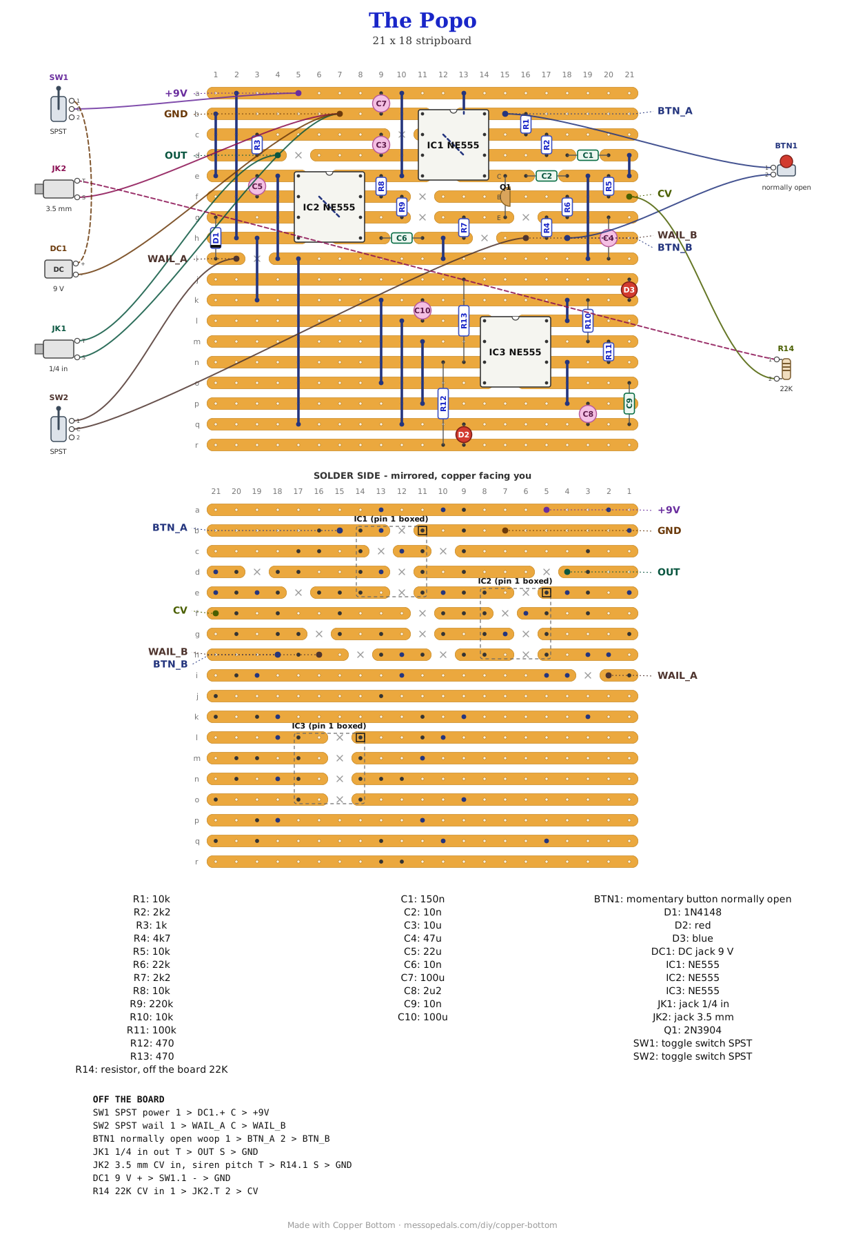
My Siren literally sounds like a police siren, so it goes in one box with my Police Lights: a cop-car siren with a woop button and a wail switch, and a red and blue wig-wag flashing over it. Both boards are built, and this is the two of them on one piece of stripboard, every part in the same hole, joined by two links so one supply feeds both. It adds a CV input on the siren's pitch, so an LFO or a sequencer can work the siren too.
What you'll need
tap to expand / collapse
The Siren's parts and the Police Lights' parts, renumbered so nothing clashes.
- 3× NE555 timer, 8-pin DIP (IC1, IC2, IC3) - spot it: NE555 on top, a notch at pin 1. IC1 must be a bipolar NE555: the siren's pitch bend leans on its internal divider, and a CMOS 7555 or TLC555 barely bends
- 1× 2N3904 NPN transistor (Q1) - spot it: a black half-cylinder. Its legs stand in one column: collector on strip e, base on f, emitter on g
- 4× 10K (R1, R5, R8, R10) - brown-black-orange
- 2× 2.2K (R2, R7) - red-red-red
- 1× 1K (R3) - brown-black-red
- 1× 4.7K (R4) - yellow-violet-red
- 1× 22K (R6) - red-red-orange. Count two resistors beside the transistor: R6 and R4 stand side by side, and leaving R6 out gives one steady note with the button and the wail switch doing nothing
- 1× 220K (R9) - red-red-yellow
- 1× 100K (R11) - brown-black-yellow
- 2× 470 ohm (R12, R13) - yellow-violet-brown, one for each LED
- 1× 150n ceramic (C1) - spot it: 154
- 3× 10n ceramic (C2, C6, C9) - spot it: 103
- 1× 10 µF, 1× 47 µF, 1× 22 µF, 1× 2.2 µF and 2× 100 µF electrolytic (C3, C4, C5, C8, C7 and C10) - spot it: the stripe marks the negative leg
- 1× 1N4148 diode (D1) - a small glass bead, band toward the wail switch
- 1× red LED and 1× blue LED (D2, D3) - plain, not self-flashing. Pre-wired LEDs on leads, soldered into their holes, are what lets them reach the face of the box
- Stripboard, 18 strips × 21 holes or larger, and solid wire for seventeen links
Off the board
- 1× SPST toggle, the power switch, in the positive lead between the DC jack and the +9V pad. The lights run whenever the box is on
- 1× DC jack, 9V center-negative
- 1× normally-open momentary button, the woop. A normally-closed one, or a four-leg tactile button wired across a joined pair, holds the siren wound up and looks like a dead button
- 1× SPST toggle, the wail switch
- 1× 1/4 in mono jack, the line out
- 1× 3.5 mm mono jack for CV, and a 22K resistor (red-red-orange) soldered between its tip and the wire to the CV pad
The layout file is the guide
Like the rest of the stripboard shelf, the build document for this one is the file itself: ↓ Download The_Popo.json - import it into Copper Bottom and the editor gives you the board picture, the placement walkthrough, the electrical checks and a printable build sheet, all from the same file. No coordinates are written out on this page on purpose: the editor is the viewer, and a number typed twice is a number that can drift.
Two links join the halves. J16 runs from the Siren's supply on strip h down to the Police Lights' supply on strip k, and J17 from the Siren's ground on strip i down to strip q. Leave either out and the lights sit dark while the siren plays. The Police Lights strips run the whole width of the board, so the empty holes on their left are copper with nothing on it, not a fault.
The netlist
Quoted verbatim from the layout file. It is the Siren's netlist and the Police Lights' netlist together, the Police Lights renumbered, the two supplies joined and the CV pad added, and every net of both built boards was checked to survive in the new board.
The off-board wiring
Eight pads leave the board.
| Pad | Goes to |
|---|---|
| +9V | The power switch; the switch's other side to the DC jack's center pin |
| GND | The DC jack's sleeve, and both jack sleeves |
| OUT | The line out jack's tip |
| BTN_A / BTN_B | The woop button's two lugs |
| WAIL_A / WAIL_B | The wail switch's two lugs |
| CV | Through the 22K to the CV jack's tip. The pad is the base of Q1, the same point the button and the wail push on |
How it works, in one breath
The siren is the Siren: IC1 makes the tone, and C4 is the motor. The button charges C4, it drains slowly back through R6 and R5, and that voltage turns on Q1, which pulls IC1's pin 5 down and raises the pitch. IC2 is a slow oscillator that presses the button for you when the wail switch is on. The lights are the Police Lights: IC3 flips its output about three times a second, lighting red going high and blue going low.
The CV goes onto the base of Q1 through 22K, so it pushes the pitch the same way the button does: more volts is higher, and it adds to the button and the wail. By the arithmetic, about 5V gives a modest rise and about 10V comes close to the full wind-up; a plugged-in 0V takes a little off the top of the button's wind-up, and a negative CV leaves the pitch at rest. None of that is measured yet.
Boxing it up
An upright 125B: red and blue across the top, the woop button in the middle, the wail and power toggles under it and the 3.5 mm CV jack at the bottom of the face, with the line out and the DC jack on the top wall. Nobody has drilled this one yet: the hole sizes come from the layout file and the parts list, and where they sit is my layout.
↓ Vertical 125B, line out and DC on top (PDF)
My layout: everything else on the face, the line out and the DC jack on the top wall.
↓ Vertical 125B, everything on the face (PDF)
The other way to drill it: DC and the line out along the bottom of the face. The woop hole is 12 mm; check your button.
Things to try
- The Siren's tweaks all carry over. C1 at 220n is lower overall, 100n higher; R7 at 1.8K raises the top of the wind-up; a bigger C5 slows the wail
- Slower or faster lights. C8 sets the flash rate: bigger is slower
- An LFO into the CV. A slow one makes a wail of its own, independent of the wail switch. Untested
The Siren and the Police Lights are Onion Madder's, both built. The CV input is a resistor into the transistor the button already drives. Drawn in Copper Bottom.