Siren
A 90s cop-car siren · Two 555s on nine strips · By Onion Madder · Mess O' Pedals
Hold the button and the pitch winds up like a motor spinning; let go and it coasts back down. Tap it quick and you get the woop. Flip the wail switch and a slow second 555 presses the button for you, up and down for as long as it is on. Two 555s, one transistor and a handful of parts on a 9 by 21 board, with a line out for an amp or a synth.
What you'll need
tap to expand / collapse
- 2× NE555 timer, 8-pin DIP (IC1, IC2) - spot it: NE555 on top, a notch or a dot at pin 1. IC1 has to be a bipolar NE555: the pitch bend leans on the 5K divider inside it at pin 5, and a CMOS 7555 or TLC555 will barely bend. IC2, the slow one, can be either
- 1× 2N3904 NPN transistor (Q1) - spot it: a small black TO-92 with one flat face, 2N3904 printed on the flat. Match its legs to the C, B and E the drawing marks
- 1× 1N4148 diode (D1) - spot it: a little glass bead with a black band. The band goes toward the bottom strip, away from IC2
- 3× 10K resistor (R1, R5, R8) - spot it: bands brown-black-orange
- 2× 2.2K resistor (R2, R7) - spot it: red-red-red. R7 sets how high the pitch goes
- 1× 1K resistor (R3) - spot it: brown-black-red
- 1× 4.7K resistor (R4) - spot it: yellow-violet-red. How fast the button spins it up
- 1× 22K resistor (R6) - spot it: red-red-orange
- 1× 220K resistor (R9) - spot it: red-red-yellow. With C5 it sets the wail speed
- 1× 150n capacitor (C1) - spot it: 154. The tone's timing cap, film or ceramic
- 2× 10n ceramic (C2, C6) - spot it: 103. One on each control pin
- 1× 47 µF electrolytic (C4) - spot it: a can with a stripe down the negative side. This is the "motor"
- 1× 22 µF electrolytic (C5) - the wail's timing cap
- 1× 10 µF electrolytic (C3) - the output cap
- 1× 100 µF electrolytic (C7) - the biggest can, across the supply
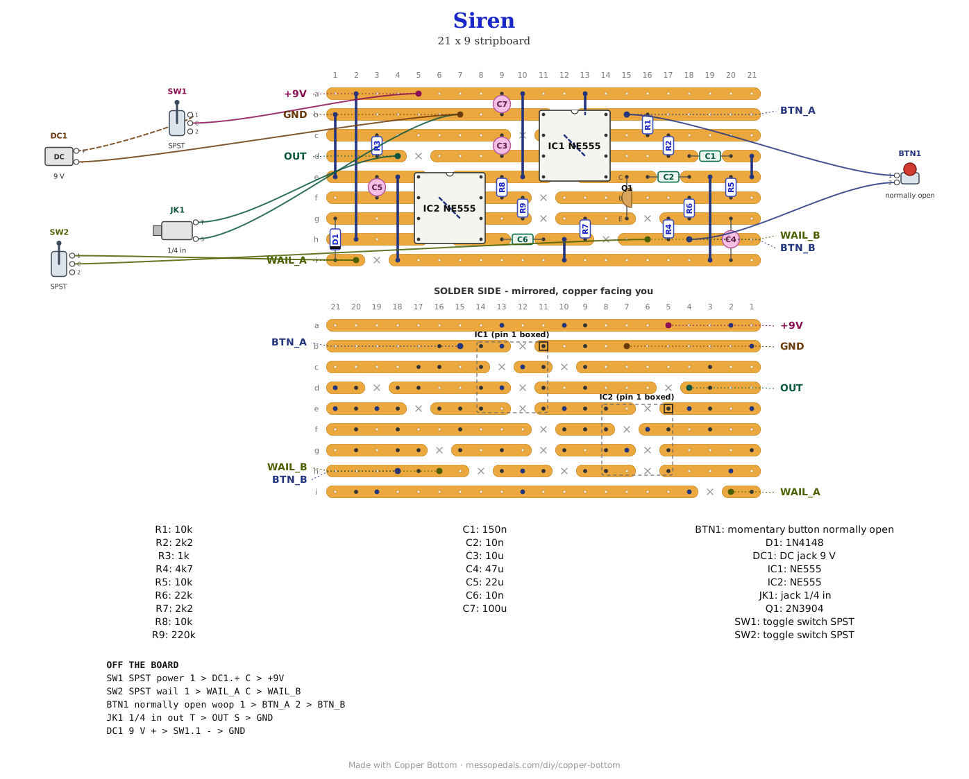
- Stripboard, 9 strips × 21 holes or larger, and solid wire for ten links. Two of them run diagonally under the chips, one under each, joining pin 2 to pin 6, so lay those before the chips go in. Every resistor stands up
Off the board
- 1× 9V DC jack, or a 9V battery and snap - spot it: on a battery snap, red lead plus, black lead minus
- 1× SPST toggle, the power switch, in the positive lead between the supply and the +9V pad
- 1× momentary pushbutton, normally open - the woop button
- 1× SPST toggle - the wail switch
- 1× 1/4 in mono jack - the output
The layout file is the guide
Like the rest of the stripboard shelf, the build document for this one is the file itself: ↓ Download Siren.json - import it into Copper Bottom and the editor gives you the board picture, the placement walkthrough, the electrical checks and a printable build sheet, all from the same file. No coordinates are written out on this page on purpose: the editor is the viewer, and a number typed twice is a number that can drift.
The two chips sit staggered, IC2 low on the left and IC1 high on the right, and share strip e: IC2's pin 8 and IC1's pin 4 both want the supply, so one strip between them does both jobs. That is most of why the board is 9 by 21.
The netlist
Quoted verbatim from the layout file. It says what each strip is supposed to be doing while you stare at it, and it carries the circuit somewhere else if you want to lay it out your own way.
The off-board wiring
Seven pads leave the board.
| Pad | Goes to |
|---|---|
| +9V | The power switch; the switch's other side to the DC jack's center pin, or the battery snap's red lead |
| GND | The DC jack's sleeve or the battery snap's black lead, and the output jack's sleeve |
| OUT | The output jack's tip |
| BTN_A | One lug of the woop button |
| BTN_B | The other lug of the woop button |
| WAIL_A | One lug of the wail switch |
| WAIL_B | The other lug of the wail switch |
How it works, in one breath
IC1 is a plain 555 astable making the tone: R1, R2 and C1 put it at about 650 Hz. Its pin 5 is the top of a divider inside the chip, and pulling that pin down makes the chip run faster. C4 is the motor. The button charges it through R4 in about a fifth of a second, and R6 and R5 drain it over a second or two once you let go. R6 and R5 also feed a slice of C4's voltage to Q1's base, so the fuller C4 is, the harder Q1 pulls pin 5 down and the higher the tone goes. R7 sets that current, which is why any 2N3904 does the same job. With the button held, the arithmetic puts the top somewhere between 1.4 and 1.7 kHz; the bench will say. IC2 is a second astable running slowly, R8, R9 and C5 giving about three and a half seconds up and three and a half down. With the wail switch closed, its output charges C4 through D1 the way the button would, so the siren winds up and coasts down on its own.
Things to try
- Lower or higher overall. C1 at 220n is lower, 100n is higher
- A different top note. R7 at 1.8K goes higher when wound up, 2.7K lower
- A heavier motor. C4 at 100 µF spins up and coasts down slower, and taps need to be a bit longer to woop. A smaller R4 spins up snappier
- Wail speed. A bigger C5 is slower, a smaller one faster
- A speaker instead of the line out. A 100 µF cap from pin 3 to an 8 ohm speaker. Untested here
- Mind the level. The output is the 555's full square wave through C3 and R3, several volts, which is hot for a line input. Start with the amp turned down
The circuit is two datasheet 555 astables and a transistor on the control pin. The layout is Onion Madder's, drawn in Copper Bottom.