Opto Duet CV
The Opto Duet with tempo and pitch CV · Two 555s on ten strips · By Onion Madder · Mess O' Pedals
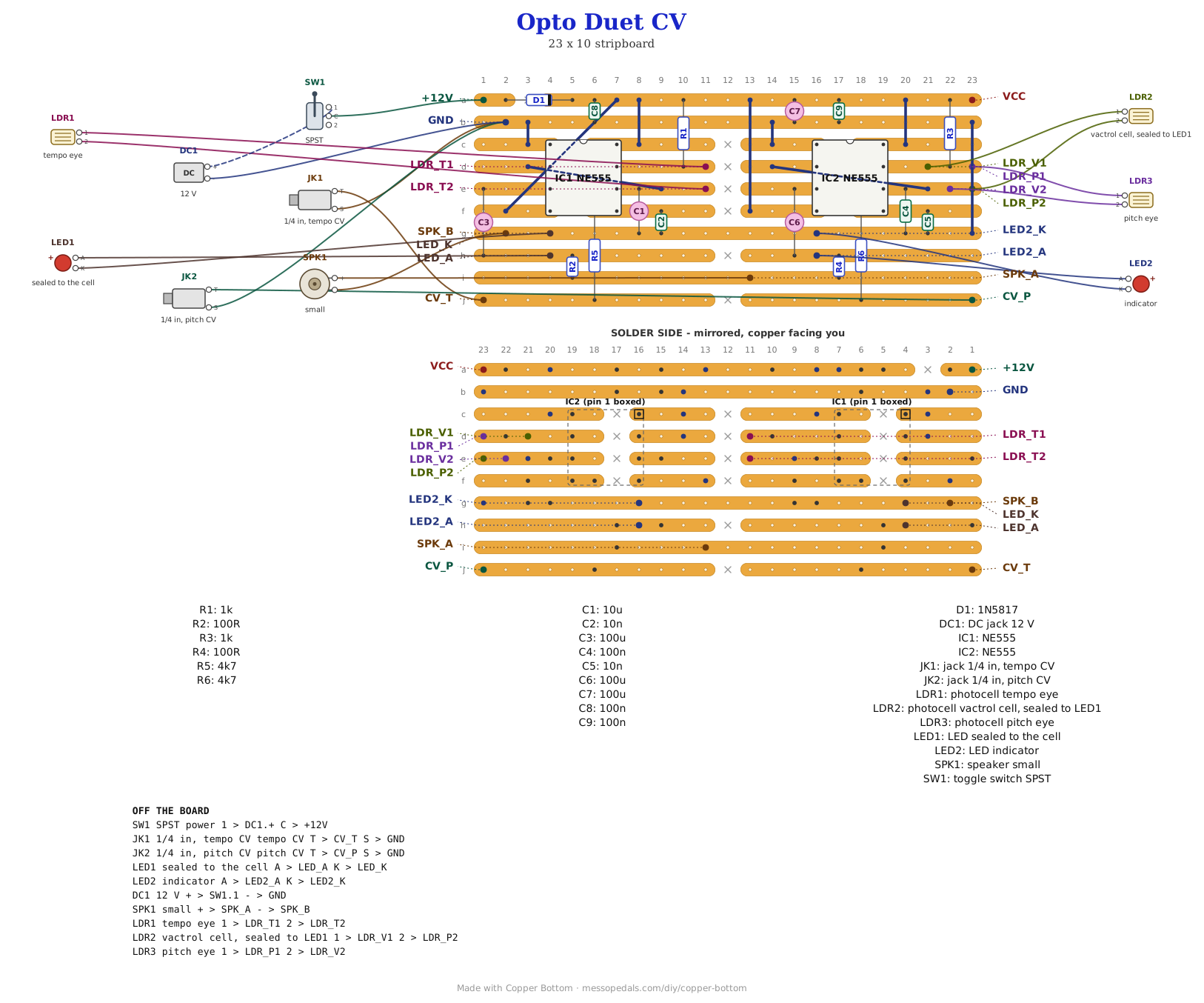
The Opto Duet is two 555s that play each other: an engine that ticks, flashing an LED sealed to a photocell, and a voice whose pitch that photocell yanks. Its tempo and pitch come from light, two eyes on the face. This one adds a CV jack for tempo and one for pitch, so an LFO, an envelope or a sequencer can push them too. It is my built v2 board, every part in the same hole, with one strip added along the bottom and two resistors. The eyes stay in. Unplugged, it plays exactly like the v2.
What you'll need
tap to expand / collapse
The Opto Duet's parts, plus two resistors and two jacks.
- 2× NE555 timer, 8-pin DIP (IC1, IC2) - spot it: NE555 on top, a notch marks pin 1
- 2× 4.7K resistor (R5, R6) - spot it: bands yellow-violet-red. The new parts. Each lies from its chip's pin 5 strip down to the bottom strip, across four strips
- 2× 1K resistor (R1, R3) - spot it: brown-black-red. One per timing chain
- 2× 100R resistor (R2, R4) - spot it: brown-black-brown. The output resistors; both stand up
- 1× 10 µF electrolytic (C1) - the engine's timing cap
- 3× 100n ceramic (C4, C8, C9) - spot it: 104. The voice's timing cap, and one across the supply beside each 555
- 2× 10n ceramic (C2, C5) - spot it: 103. On each control pin, which is where the CV now arrives
- 3× 100 µF electrolytic (C3, C6, C7) - two output couplers and one across the rails
- 1× 1N5817 Schottky (D1) - spot it: black body, gray band. In the +12V lead, band toward the chips
- Stripboard, 10 strips × 23 holes or larger, and solid wire for nine links
Off the board
- 2× 1/4 in mono jack, one for tempo CV and one for pitch CV - tips to CV_T and CV_P, sleeves to ground
- 3× photocell (LDR), 2× LED, heat-shrink for the vactrol, a speaker or an output jack, a power toggle, a DC jack and a 12V center-negative supply - all exactly as the Opto Duet lists them, and the reasons are there too
The layout file is the guide
Like the rest of the stripboard shelf, the build document for this one is the file itself: ↓ Download Opto_Duet_CV.json - import it into Copper Bottom and the editor gives you the board picture, the placement walkthrough, the electrical checks and a printable build sheet, all from the same file. No coordinates are written out on this page on purpose: the editor is the viewer, and a number typed twice is a number that can drift.
Copper Bottom will show four warnings, and they are the v2's. C1 crowds C2 and the edge of IC1, and R2 and R4 have only one hole to span so they stand up. All four are on the board I built, which went together and plays. Nothing on the new strip adds one.
The netlist
Quoted verbatim from the layout file. It is the v2's netlist with R5 and R6 joined to the two control-pin nets and two nets added, and it was checked net by net that every v2 net survives in the new board.
The off-board wiring
Sixteen pads leave the board: the Opto Duet's fourteen, wired exactly as its page explains, and two new ones.
| Pad | Goes to |
|---|---|
| CV_T | Tempo CV jack tip. R5 takes it into the engine's pin 5. The sleeve goes to GND |
| CV_P | Pitch CV jack tip. R6 takes it into the voice's pin 5. The sleeve goes to GND |
| +12V / GND | The supply through the power toggle, as on the Opto Duet; the two CV sleeves join GND |
| VCC | Nothing. A test point that tells Copper Bottom the strip is a supply |
| SPK_A / SPK_B | Speaker, or the output jack's tip and sleeve |
| LED_A / LED_K | The LED sealed face to face with the vactrol cell |
| LED2_A / LED2_K | The indicator LED |
| LDR_T1 / LDR_T2 | The tempo eye |
| LDR_V1, LDR_P1 / LDR_V2, LDR_P2 | The vactrol cell and the pitch eye, in parallel across the same two strips |
How the CV gets in, in one breath
Pin 5 of a 555 sets the voltage its timing cap has to reach before the output flips. It normally sits at two thirds of the supply, behind the chip's own resistors, about 3.3K. R5 and R6 let a CV pull it up or down: through 4.7K, every volt of CV moves pin 5 by about 0.4 of a volt. More volts means slower tempo and lower pitch, the opposite of the eyes, where more light is faster and higher. All of it is the 555's arithmetic on a 12V supply, not a measurement:
- Unplugged, nothing touches pin 5 and it plays as the v2
- A plugged-in 0V pulls pin 5 down and already runs it about 1.4 times faster than unplugged. Plugging in a silent cable changes the sound
- 10V slows it to about 0.87 of the unplugged rate
- Eurorack's -5V runs it about 1.7 times faster. Even -10V leaves pin 5 above ground, so no protection diode is needed
- The eyes still set where it sits; the CV moves it from there. A photocell in bright light and a CV pushing the other way will fight
The 10n on each control pin was already there. With the 4.7K it passes CV up to about 8 kHz, so the pitch input takes audio-rate wobble as well as a slow sweep. On the engine, the CV changes how long each flash lasts as well as how often it comes, because only the charging half of a 555's cycle listens to pin 5.
Boxing it up
A 125B stood upright, like the Opto Duet's vertical box: the two eyes and the LED across the face, the power toggle below them, DC and the output along the bottom, and the two CV jacks on the top wall, because the face is only 42 mm wide once the lid lip is clear. Nobody has drilled this one yet: the hole sizes come from the layout file, and where they sit is the house layout applied to it.
↓ Vertical 125B, CV jacks on top (PDF)
The layout: the CV jacks on the top wall, everything else on the face where the Opto Duet has it.
↓ Vertical 125B, everything on the face (PDF)
The other way to drill it: the CV jacks two across above DC and the output.
Things to try
- One of my LFOs into pitch. The Utility LFO or the Dual-Wave LFO into CV_P wobbles the voice on top of what the vactrol is already doing
- The engine into its own pitch. A patch cable from the output to the pitch CV jack is untested: expect it to fight the vactrol rather than agree with it
- More range. A smaller R5 or R6 lets the CV push harder: at 2.2K, every volt moves pin 5 by about 0.6, and a plugged-in 0V runs it about 1.6 times faster than unplugged. Untested, so try it in the board before you trim the leads
The Opto Duet is Onion Madder's; the CV inputs are the 555 datasheet's control pin. The layout is the built v2's with one strip added, drawn in Copper Bottom.