MFOS Micro Sample & Hold
Article by Ray Wilson · Music From Outer Space
A compact sample-and-hold module, small enough to add onto an existing synth, with a built-in clock and a glide control.

Introduction
I have revised the Micro Sample and Hold circuit and PCB. You can find documentation for both versions on the site. I am only selling the newer version of the PC board. The documentation related to the older version will remain online to support people who built that version.
The MFOS Micro-Sample & Hold is a nice addition to your voltage controlled sound generator project whether it's a Synth-DIY Experimenter PC Board project, Sound Lab Mini-Synth or large modular synth project. It is as simple as a Sample & Hold can be yet features variable sample rate and output voltage glide (portamento). Its a simple way to add more flexibility to your synthesizer.
Circuit Description
Voltage to be sampled is applied to the input which is one end of R2 (100K linear taper potentiometer). The other end of R2 is grounded and thus the level of signal applied to buffering level shifter U1-A and associated components is controlled by R2. Signals applied to the sample and hold (at point X1) can oscillate about ground but should not exceed about +/-5.5 volts. That is why the design was changed to allow for higher level signals since they can be attenuated by adjusting R2. If the voltage at pin 1 of U1-A goes below ground Q1 can clip the signal and improper sampling results. R1 and R3 comprise a voltage divider which causes the applied attenuated signal to be effectively cut down to half of it's level. This signal is applied to U1-A (1/4 LF444 quad op amp) where it is level shifted and given a gain of about 1.5. Here you can see the comparison of the input signal to the signal at pin 1 of U1-A.
Q1 N-Channel JFET 2N5457 acts like a closed switch (between source and drain) when it's gate is brought slightly above ground by differentiated pulses which are generated by picking off the front end of the rectangle wave output by U1-D sample clock generator. Normally (when no pulse is being applied) the gate of Q1 is held at about -3.6V by resistor network R7, R6 and R13. The voltage that is present at the source of Q1 passes through to the drain and charges (or discharges as the case may be) C1 where the sampled voltage is held until the next pulse hits the gate. U1-B buffers the sample held on the cap. The LF444CN chip has ultra low input current which allows the sample to sit on the cap and be buffered by U1-B for quite some time. With no pulse applied to the gate of Q1 it essentially acts like an open switch (source to drain) and the voltage on C1 does not leak back through the transistor. Buffer U1-B applies gain of about 1.5 and also level shifts the signal so that it approximates the original input level and oscillates about ground.
Sample clock generator U1-D and associated components works as follows. If we begin our analysis imagining that the output of U1-D just went low (to about -11V) we see that the voltage level applied to U1-D pin 12 is about -1.9 volts. C8 (10uF aluminum or tantalum electrolytic capacitor) which had previously been charged (remember U1-D just went low and was high prior to that transition) to well above ground (actually to about 2V) begins to discharge via R15 and 1M Sample Rate adjust pot R16. When C8 discharges to below -1.9 volts (the level on pin 12 remember) the output of U1-D shoots to about +11V causing the voltage at U1-D pin 12 to go to about +1.9V and also causing C8 to charge from it's previous voltage (about -2V) towards V+ via D2 (1N914 high speed diode) and R15 (4.7K resistor). When C8 charges to above the level on U1-D pin 12 (about +2V), U1-D's output shots low again and this cycle continues. The output of U1-D is an asymmetric rectangular pulse wave due to D2 which allows the positive excursion of U1-D to charge C8 without the effect of 1M Sample Rate pot R16. Thus the high time is limited to about 20 mS and the low time depends on the setting of 1M Sample Rate pot R16. The rate of the sample clock can be varied from about 0.33 hertz to about 30 hertz. The sample clock's output is fed through D3 (1N914) and dropped on R18 (100K resistor) and then connected to the jack for the trigger output.
The LF444CN's output has a bit of a hard time driving 2mA through the LED but works fine and is within the op amps operational parameters. Use a high efficiency LED for best results. The circuit drives a general purpose LED just fine IMHO.
How the sample and hold works
Input voltage
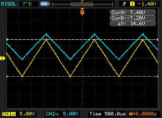
Level shifted voltage
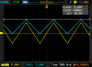
Sampling the level shifted signal
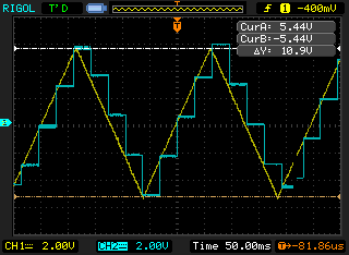
Low frequency input, high sample rate
The differentiated trigger pulse
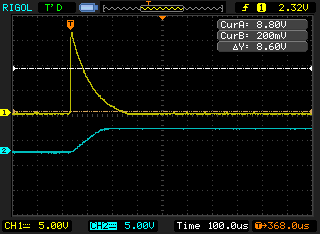
U1D pins 12 and 13
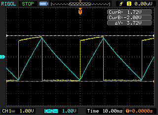
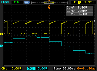
Trigger output versus sampled voltage
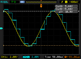
Glide
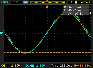
The output of U1-B feeds the CV Out 1 banana jack (or whatever jack you use) and also is input to the glide circuit comprised of U1-C and associated components. R14 (1M audio taper pot) in series with R12 (220 ohm resistor) is used to adjust the charge and discharge time of C7 (glide effect). The high input impedance of U1-C simply buffers the voltage on C7. The scope photos show the effect of adjusting R14 from no glide to more and more glide.
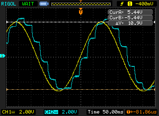
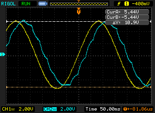
Schematic
View the Micro Sample & Hold schematic as PDF »
The schematic, read out in words
tap to expand / collapse
Ray's schematic is the PDF above. The drawing itself has no words a screen reader can reach, so this is it read out stage by stage. The title block reads Micro Sample And Hold Rev 1, Design by Ray Wilson, Copyright Music From Outer Space 2011. The input is marked with an expected triangle wave between +5V and -5V, and the transistor inset shows a TO-92 package, PN4391, MPF102 or 2N5457, pins G, S, D left to right. Rails are +12V and -12V.
Input stage
- R2, 100K panel pot: lug 3 to the Input jack, lug 1 to ground, lug 2 (the wiper) to X1.
- X1 to R1 100K, then R3 100K from that node to ground.
- The node goes to U1-A pin 3, the non-inverting input. U1 is an LF444, powered +12V on pin 4 and -12V on pin 11.
- R4 560K from -12V into the U1-A feedback node, with R5 200K in the same network.
Sample switch
- U1-A pin 1 out to the source of Q1, a 2N5457.
- Q1 drain to C1, .005uF polystyrene, to ground, and on to U1-B pin 5.
- Q1 gate: R6 100K and R7 470K, R7 returning to -12V. C4 .001uF feeds the gate from the clock.
- U1-B pins 5, 6, 7. R8 150K from +12V into the feedback node, R9 75K in the feedback path.
- U1-B pin 7 goes to CV Out 1 and to X2.
Clock
- U1-D pins 12, 13, 14. R10 100K to ground in the pin 13 network, R11 470K feedback, R13 100K and D1 1N914 in the pin 13 network.
- C4 .001uF couples the U1-D output edge to the Q1 gate. C8 10uF electrolytic from the pin 13 node to -12V.
- R15 4.7K from the U1-D output to X5. D2 1N914 bridges X5 and X6, cathode at X5, anode at X6.
- R16, 1M panel pot, Sample Rate: lugs 1 and 2 both to X5, lug 3 to X6.
- D3 1N914 from the U1-D output, anode on the board side, cathode to X7. X7 to the Trigger Output jack, with R18 100K from X7 to ground.
- R17 10K from the U1-D output to X8. X8 to the LED1 anode; LED1 cathode to -12V. The LED is boxed as Panel Mounted Sample Rate Indicator.
Glide
- X2 to R14 lugs 1 and 2, tied together. R14 is 1M, labeled Glide. Lug 3 to X3.
- X3 to R12 220 ohm, then to U1-C pin 10. C7 .1uF from that node to ground.
- U1-C pins 8, 9, 10 as a follower. Pin 8 to X4, and X4 to CV Out 2.
Supply decoupling
- +12V rail: C2 .1uF and C3 1uF to ground.
- -12V rail: C5 .1uF and C6 1uF to ground.
PC Board
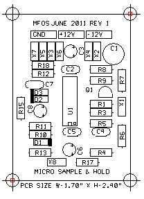
Parts placement (silkscreen)
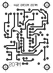
Top copper
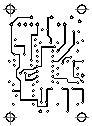
Bottom copper
Board Assembly
The diodes are 1N914 (the 1 and 4 are obscured in the image).
Assembly drawing - legend view (PDF) »
Assembly drawing - value view (PDF) »
The board drawings, read out in words
tap to expand / collapse
Both assembly drawings are the same board, 1.70 by 2.40 inches, silkscreened MFOS JUNE 2011 REV 1 and MICRO SAMPLE & HOLD. The legend view prints designators, the value view prints values in the same places. Read out here so the PDFs are not the only copy.
Pads
- Along the top edge, left to right: GND, +12V, -12V.
- Upper row, left group: X7, X5, X3, X6. Upper row, right group: X4, X2.
- Right edge, mid-board: X1. Bottom edge, left of center: X8.
- Four corner mounting holes, drawn as crosshair targets.
Where the parts sit
- Top row under the pads: R18 with R12 below it on the left, R8 with R9 below it on the right.
- Right edge, top to bottom: R7, X1, R6. Top right: C1 (the large round footprint), C3 (electrolytic, + marked), C2.
- Left edge, top to bottom: C7, D3, D2, R15, C8 (electrolytic, + marked).
- Center: U1, the LF444, printed vertically. Right of U1: Q1 (D-shaped footprint), R1, R3, R5, C4. Left of U1: R11, R10, D1, R13.
- Bottom: C5, C6 (+ marked), R4, X8, R17.
Values in the value view
- R1 100K, R3 100K, R4 560K, R5 200K, R6 100K, R7 470K, R8 150K, R9 75K, R10 100K, R11 470K, R12 220 ohm, R13 100K, R15 4.7K, R17 10K, R18 100K.
- C1 .005uF, C2 .1uF, C3 1uF, C4 .001uF, C5 .1uF, C6 1uF, C7 .1uF, C8 10uF.
- D1, D2, D3 1N914. Q1 2N5457. U1 LF444.
Panel
Here are the essential details to wiring the Micro Sample & Hold to a panel for stand-alone operation. It makes a great modulation source for the Synth-DIY Experimenter Board, the Sound Lab Mini-Synth or your modular synth.
The panel drawing, read out in words
tap to expand / collapse
The PDF is two drawings: an example panel layout on the left and the same panel from behind on the right, every board pad wired to a lug. Read out here.
Front panel
- Panel legend at the top of the plate: Micro Sample & Hold.
- Top left: Input Level knob, dial marked 0 through 10. Top right: Sample Rate knob, same dial.
- Middle left: Voltage Input jack. Middle right: Glide knob. A small unlabeled circle between them is the LED.
- Bottom row, left to right: Triggers Out, CV Out 1, CV Out 2 jacks.
Rear panel wiring
Lug 1 is the counter-clockwise end of each pot, lug 3 the clockwise end; the drawing prints a CW arrow on each.
- Board pad X1 to R2 (Input Level, 100K linear) lug 2, the wiper.
- R2 lug 3 to the Voltage Input jack terminal.
- R2 lug 1 to panel ground.
- Board pad X5 to R16 (Sample Rate, 1M linear) lug 1.
- A short jumper from R16 lug 1 to R16 lug 2, tying the wiper to that end.
- Board pad X6 to R16 lug 3.
- Board pad X2 to R14 (Glide, 1M audio) lug 1.
- A short jumper from R14 lug 1 to R14 lug 2, tying the wiper to that end.
- Board pad X3 to R14 lug 3.
- A second wire from board pad X2 to the CV Out 1 jack terminal. X2 is the buffered sample-and-hold output, so it feeds the glide pot and CV Out 1 from the same net.
- Board pad X4 to the CV Out 2 jack terminal.
- Board pad X7 to the Triggers Out jack terminal.
- Board pad X8 to the LED1 anode, the longer leg.
- LED1 cathode, the flat-side leg, to -12V.
- Every jack sleeve to panel ground.
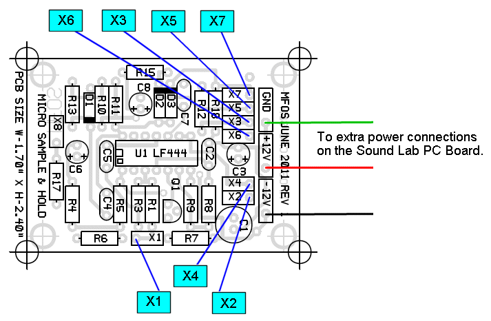
Connecting it to the Sound Lab
Here are the essential details to wiring the Micro Sample & Hold to the Sound Lab Mini Synth Plus.
Which power supply
A diyer brought a good point to my attention. The "Micro Sample And Hold" board is marked +/-12V and the Sound Lab is marked +/-9V. His question was "Which should I use?". The answer is... either. Both boards should run off of the same power supply whether it is two 9V batteries wired as +/-9V or a bipolar power supply (in the range of +/-9V to +/-15V). There will be no degradation in the operation of the Micro S&H running off of a +/-9V battery supply. The advantage of using a wall wart powered supply is that with batteries you will get a variation in performance as they discharge whereas the wall wart supply is always the same. So there you have it and sorry for any confusion this caused. That's me uttering "DOH!" by the way. :-)
That paragraph is from the Sound Lab Mini-Synth PLUS page on Ray's site, where the question came up.
Parts List
| Qty. | Description | Value | Designators |
|---|---|---|---|
| 1 | LF444 Quad Op Amp | LF444 | U1 |
| 1 | 2N5457 N Channel JFET | 2N5457 | Q1 |
| 3 | 1N914 Diode | 1N914 | D1, D2, D3 |
| 1 | General Purpose LED | Red LED | LED1 |
| 1 | Linear Taper Potentiometer | 100K | R2 |
| 1 | Linear Taper Potentiometer | 1M | R16 |
| 1 | Audio Taper Potentiometer | 1M | R14 |
| 6 | Resistor 1/4 Watt 5% | 100K | R1, R3, R6, R10, R13, R18 |
| 1 | Resistor 1/4 Watt 5% | 10K | R17 |
| 1 | Resistor 1/4 Watt 5% | 150K | R8 |
| 1 | Resistor 1/4 Watt 5% | 200K | R5 |
| 1 | Resistor 1/4 Watt 5% | 220 ohm | R12 |
| 1 | Resistor 1/4 Watt 5% | 4.7K | R15 |
| 2 | Resistor 1/4 Watt 5% | 470K | R7, R11 |
| 1 | Resistor 1/4 Watt 5% | 560K | R4 |
| 1 | Resistor 1/4 Watt 5% | 75K | R9 |
| 1 | Capacitor Alum. Electrolytic | 10uF | C8 |
| 2 | Capacitor Alum. Electrolytic | 1uF | C3, C6 |
| 1 | Capacitor Ceramic | .001uF | C4 |
| 3 | Capacitor Ceramic | .1uF | C2, C5, C7 |
| 1 | Capacitor Polystyrene Radial Leads | .005uF | C1 |
| 4 | Banana Jacks | ||
| 3 | Pot Knobs |
All work © Ray Wilson / Music From Outer Space - musicfromouterspace.com. The Micro Sample & Hold, its circuit, text and images are Ray's.
Mirrored and recoded by Mess O' Pedals to preserve Ray's work and keep it accessible. Only the HTML is mine - the design, the words, and the wit are all Ray Wilson's.