Dead-Bug Hive
A six-oscillator CD40106 drone box, point-to-point · By Onion Madder · Mess O' Pedals
One chip, six oscillators, an unholy amount of drone. The CD40106 is a hex Schmitt-trigger inverter - six little logic gates that, with one resistor and one cap each, each turn into a square-wave oscillator. Wire up all six, mix them together, and you've got a whole hive of detuned tones beating against each other. Built dead-bug, of course — legs flattened out flat and every part soldered straight to them. No breadboard, no PCB.
This is build two in the dead-bug series, after the Dead-Bug Mosquito. Same rules, same vape-pack power - and if you've seen the MFOS Weird Sound Generator I mirror, you've already met this chip: the WSG runs on 40106 oscillators too.
⚠ Before you start tap to expand / collapse
Hot iron, obviously. 350°C of don't-grab-that. Ventilate, don't breathe the flux smoke, park it in its stand every time.
CMOS has one hard rule: never leave an unused gate input floating. Any inverter you don't turn into an oscillator, tie its input to ground. Floating CMOS inputs draw current, buzz, and can even latch up. It's in Step 3 - just don't forget it.
Mind polarity on the electrolytic output cap and your power source - backwards electrolytics bulge or pop.
If you power it from a salvaged lithium pack, the usual cell cautions apply - see Do You Want to Survive the Vapocalypse?
How it works, in one breath
A Schmitt-trigger inverter flips its output opposite to its input - but with hysteresis, meaning it snaps high and low at two different thresholds instead of one. Hang a resistor from an inverter's output back to its input, and a capacitor from that input to ground, and the cap endlessly charges and discharges between the two thresholds. That's a relaxation oscillator - a square wave, no crystal, no fuss. The resistor sets the pitch (bigger = slower), the cap sets the range (bigger = lower). The 40106 gives you six of these in one 14-pin chip, so you can stack six voices and let them fight.
What you'll need
New to the parts? Each line notes how to spot it - the printed marking, the package, or the polarity clue.
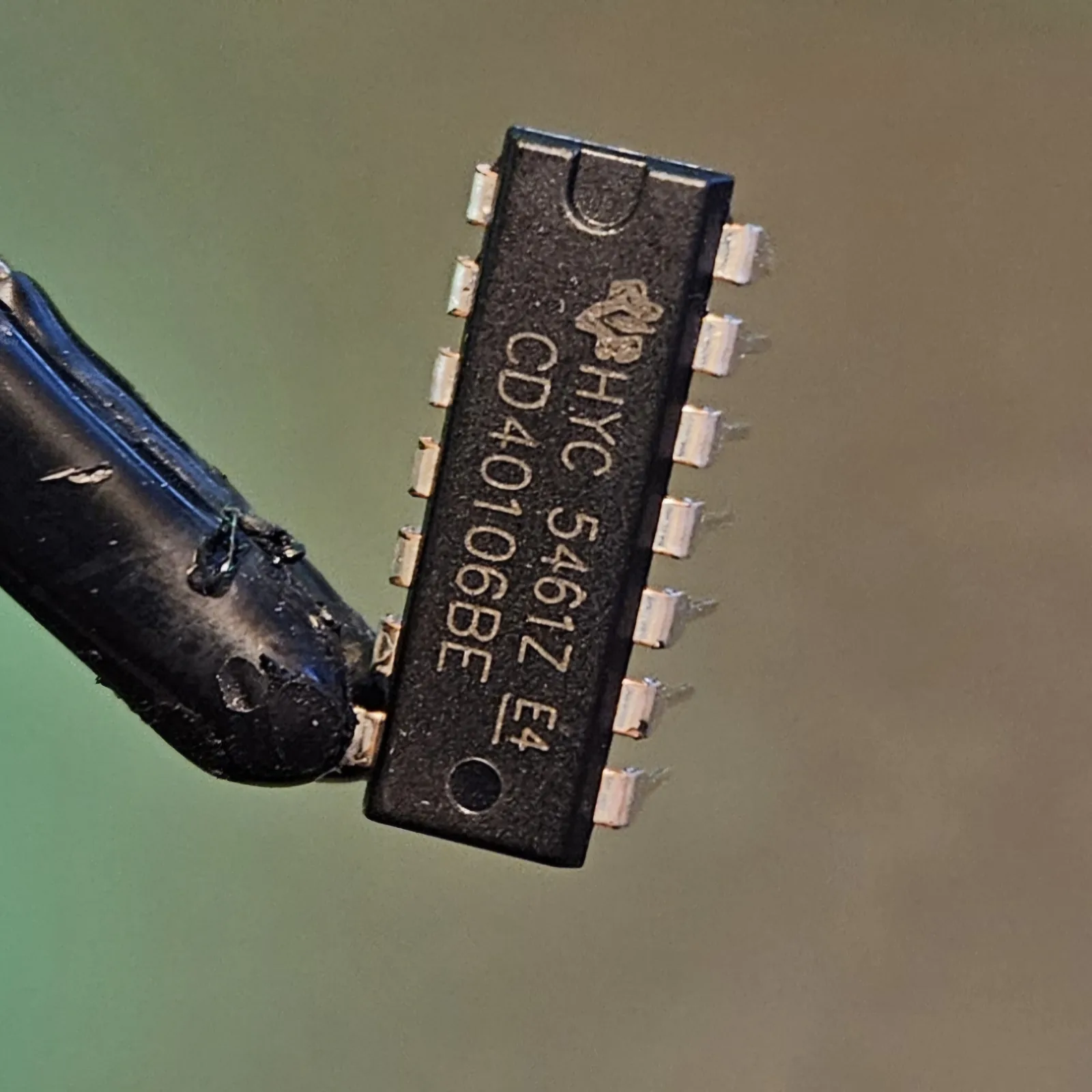 1× CD40106 (a.k.a. CD40106B / MC14106) hex Schmitt inverter, 14-pin DIP - spot it: CD40106 printed on top; a notch marks pin 1
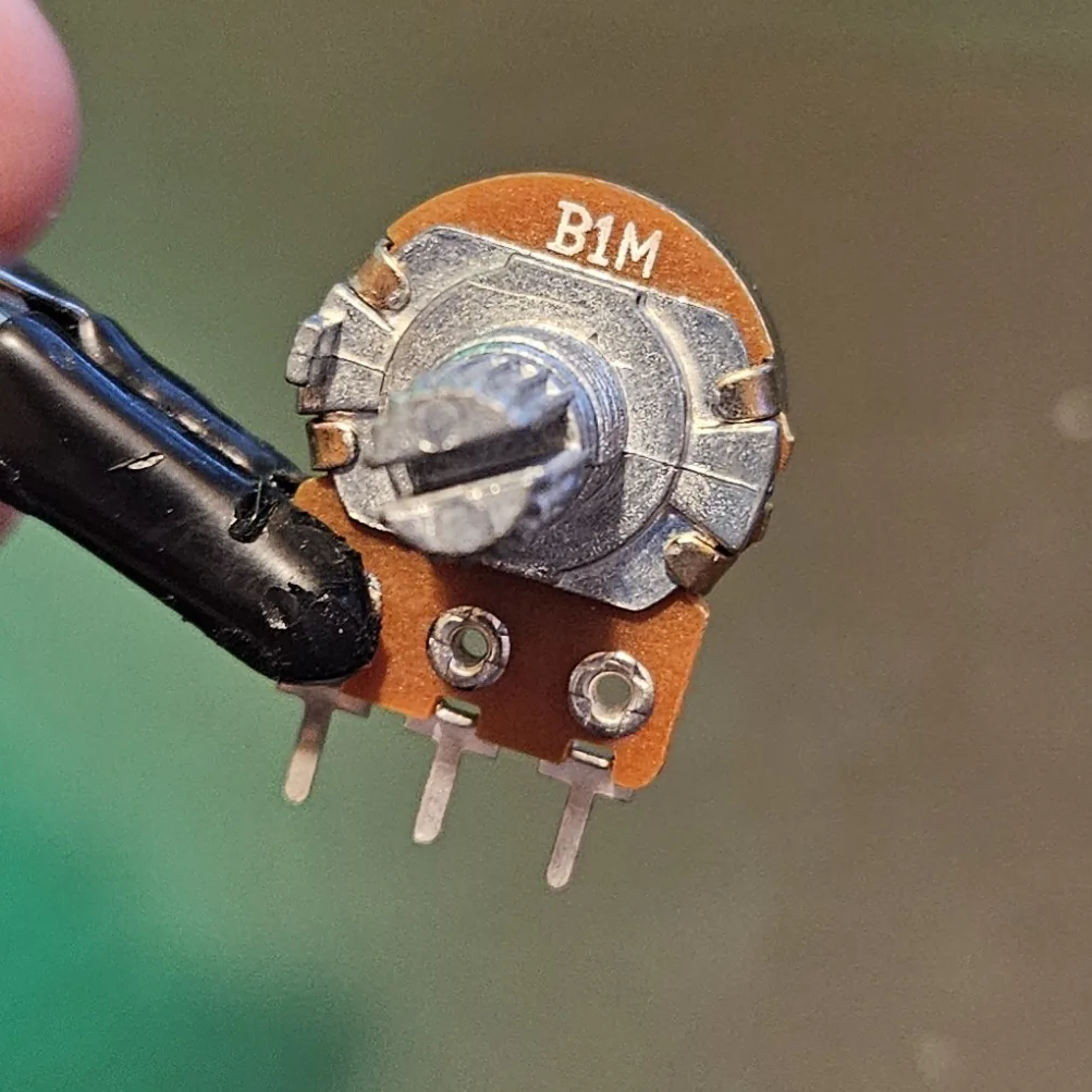 6× 1M pots for playable pitch (with a ~1K–10K series resistor each so they never hit zero). Spot it: pots are marked B = linear taper (use these), value after
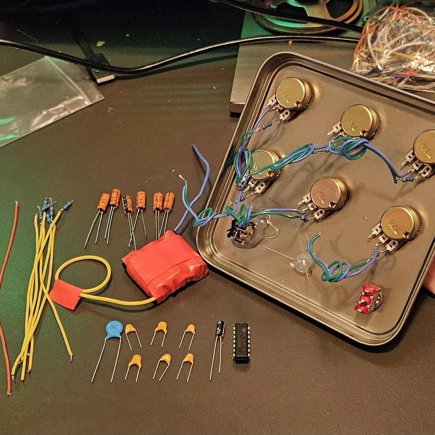
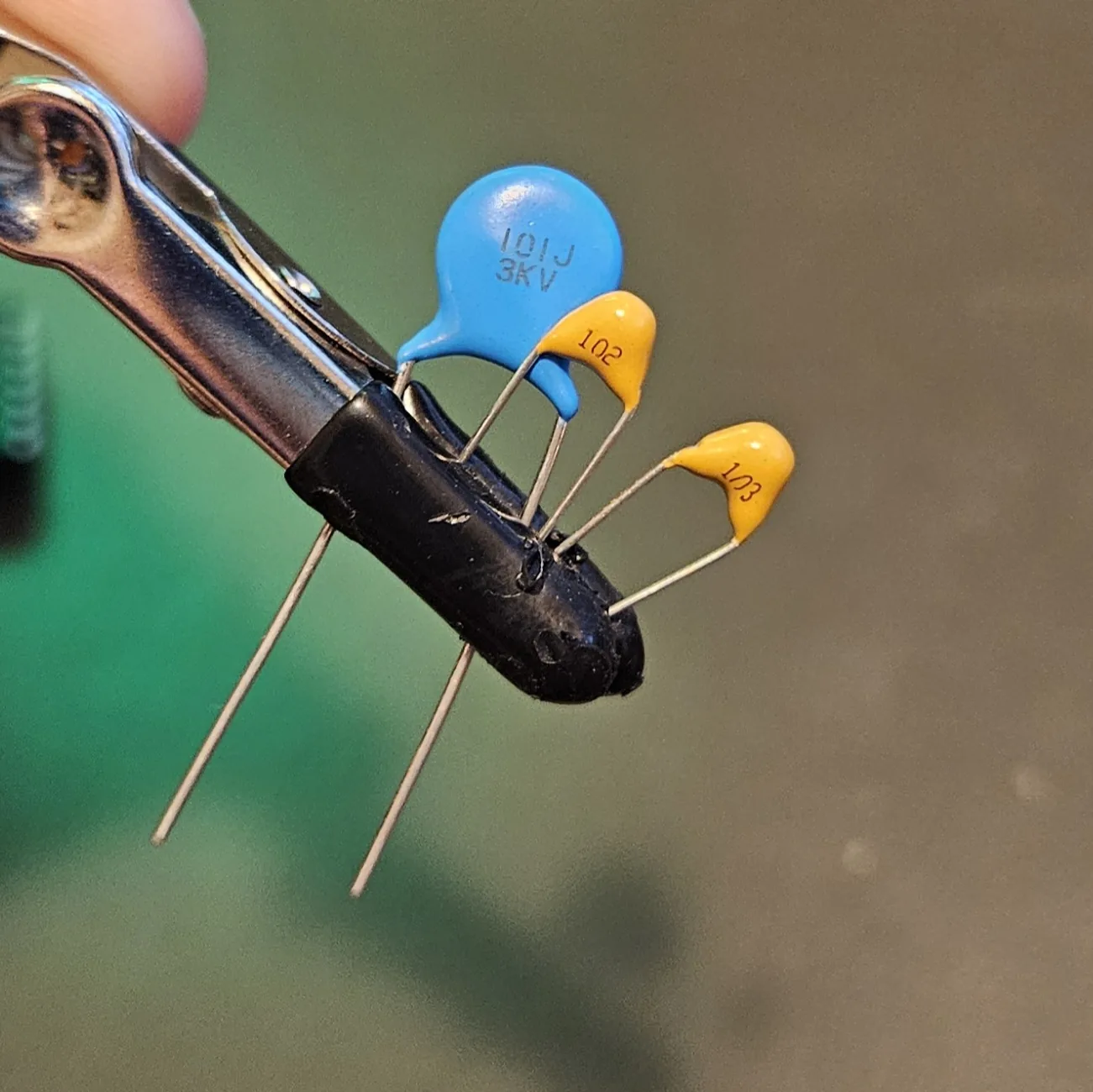 6× Ceramic capacitors, one value per voice - I run the whole ladder: 101 (100pF, highest whistle), 102, 103, 104, 105, 106 (10 µF, slow LFO clicks). Six voices, six values, and the spread is what stops it sounding like one fat buzz. Spot it: the printed code is the value - and they don't have to match each other to work. My 101 is a big blue disc marked 101J 3KV simply because that's the only 100pF I had; it sits next to little yellow ones and behaves identically. Read the number, ignore the packaging.
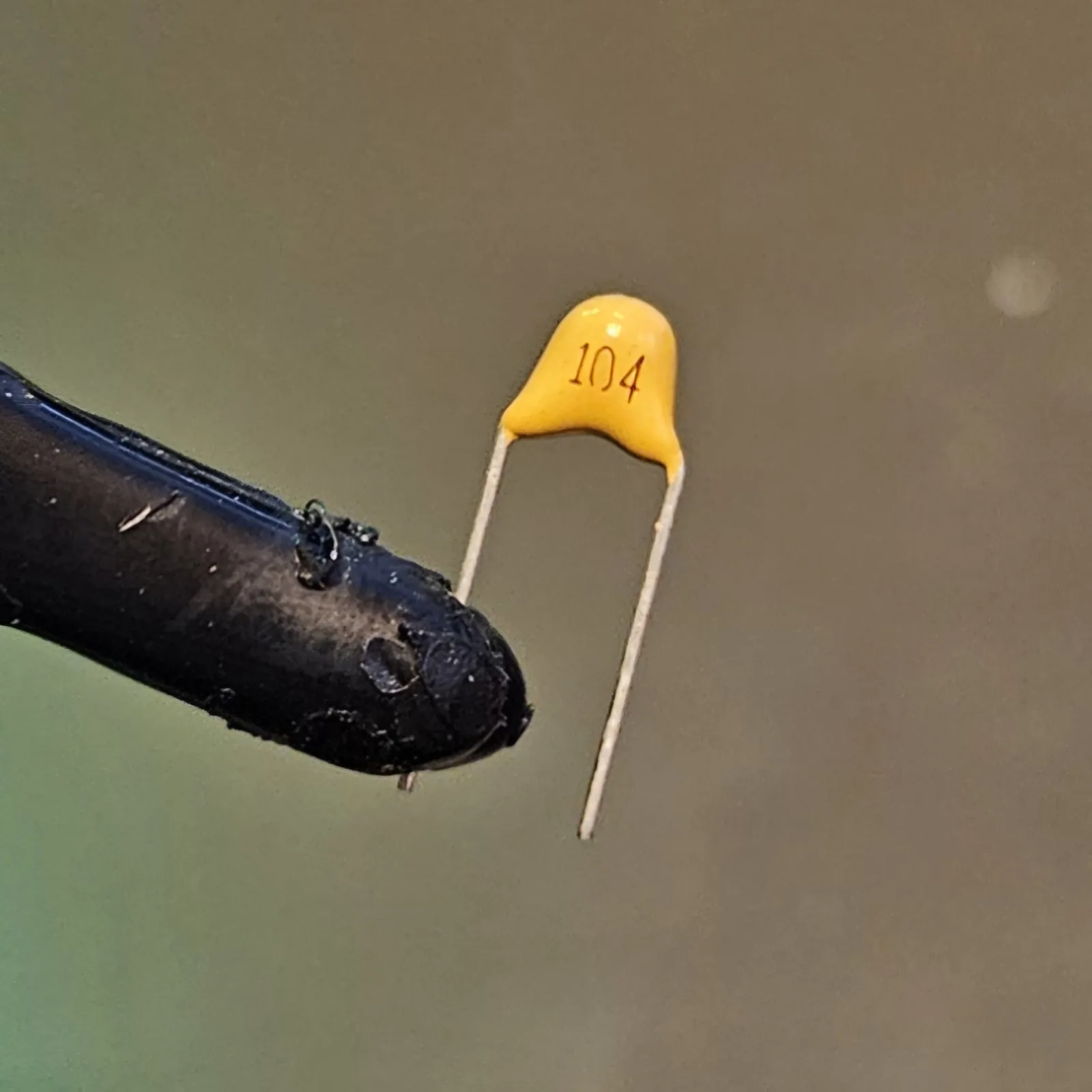 1× 0.1 µF ceramic - supply decoupling (printed 104)
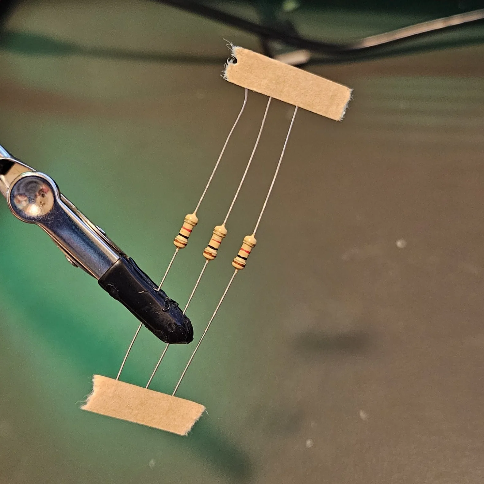 6× Mixing resistors, ~10K, one per voice you use - bands brown-black-orange, or meter them; non-polar
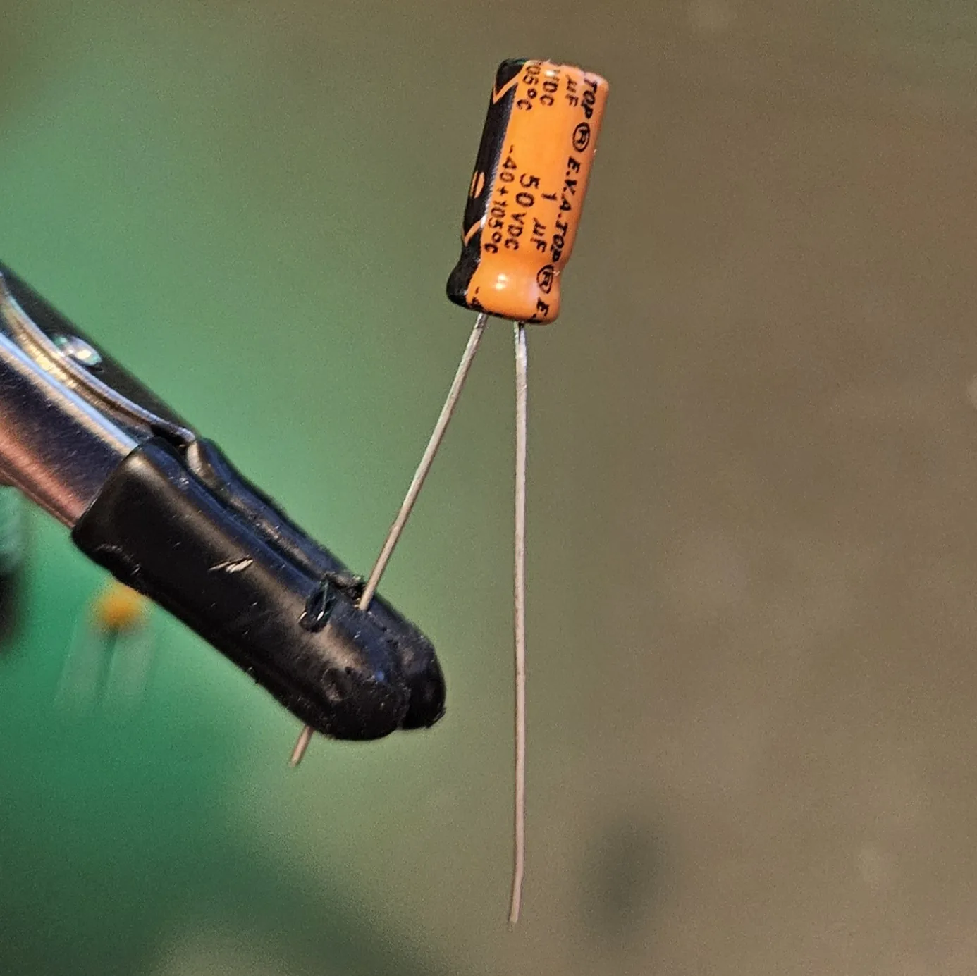 6× Mixing capacitors, one per voice - 1 µF non-polarised (NP / bipolar) is the one to reach for. Audio swings both ways, so a cap that doesn't care about direction is the safe choice here. Spot it: NP caps are usually printed NP or BP on the body
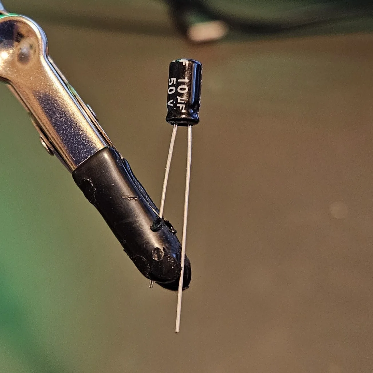 1× 10 µF electrolytic - output DC-blocker. Spot it: a little can; the stripe marks the minus leg, longer leg is +
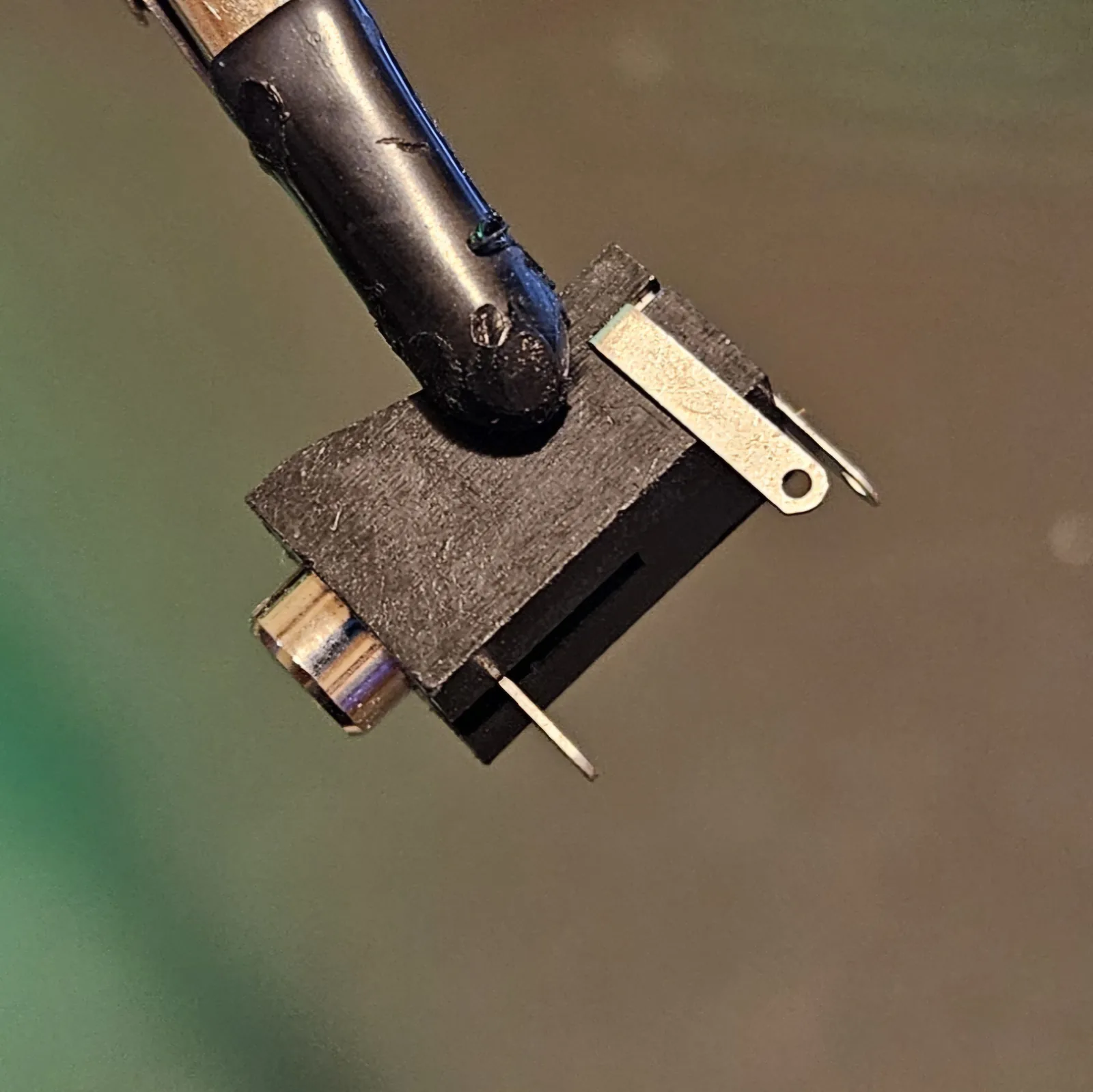 1× Output: a small speaker + an LM386 amp (an 8-pin DIP printed LM386) for real volume — that's the Dead-Bug Hornet — OR a jack to an amplifier - see Step 7
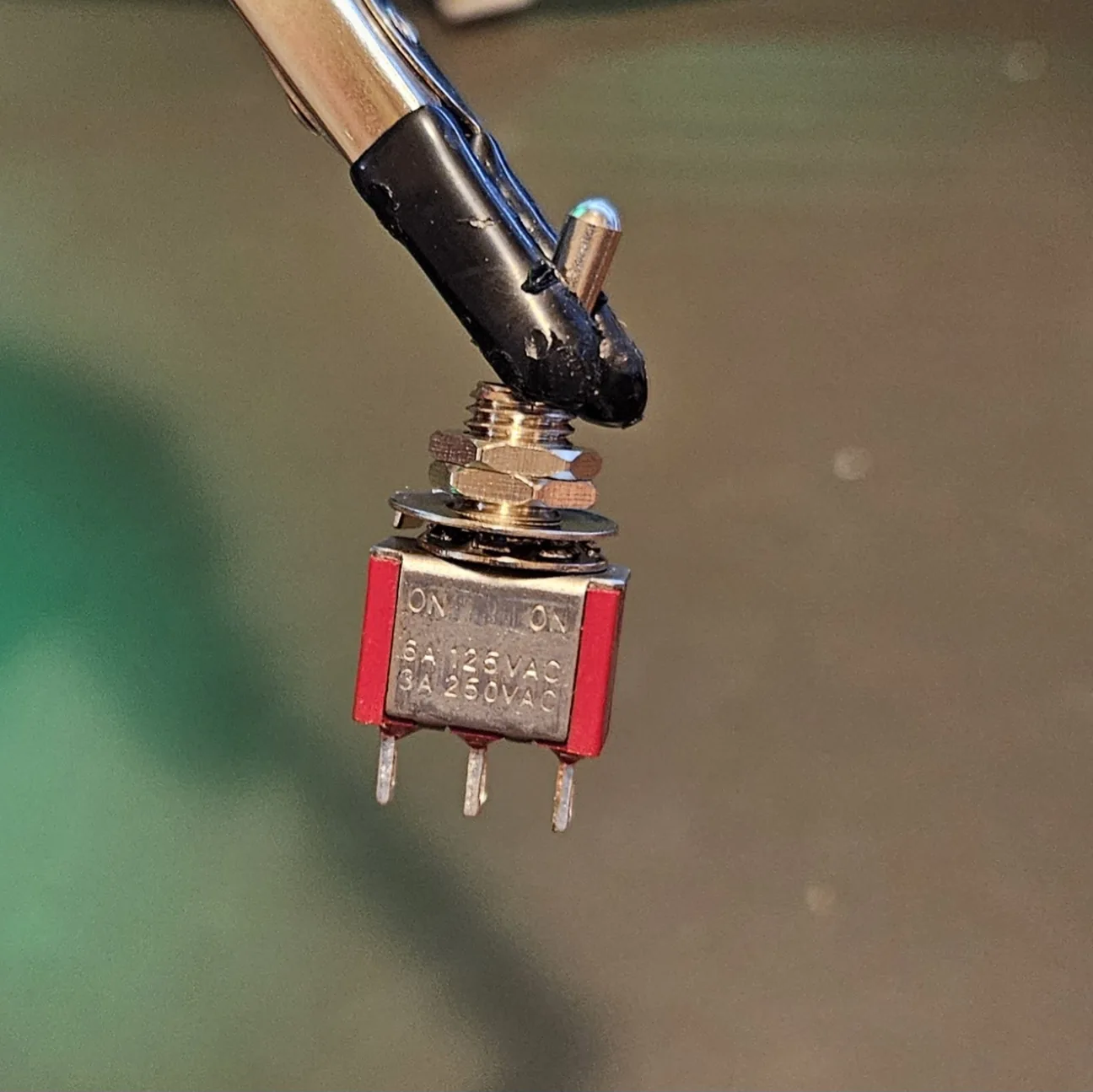 1× SPST toggle for on/off - a 2-lug switch
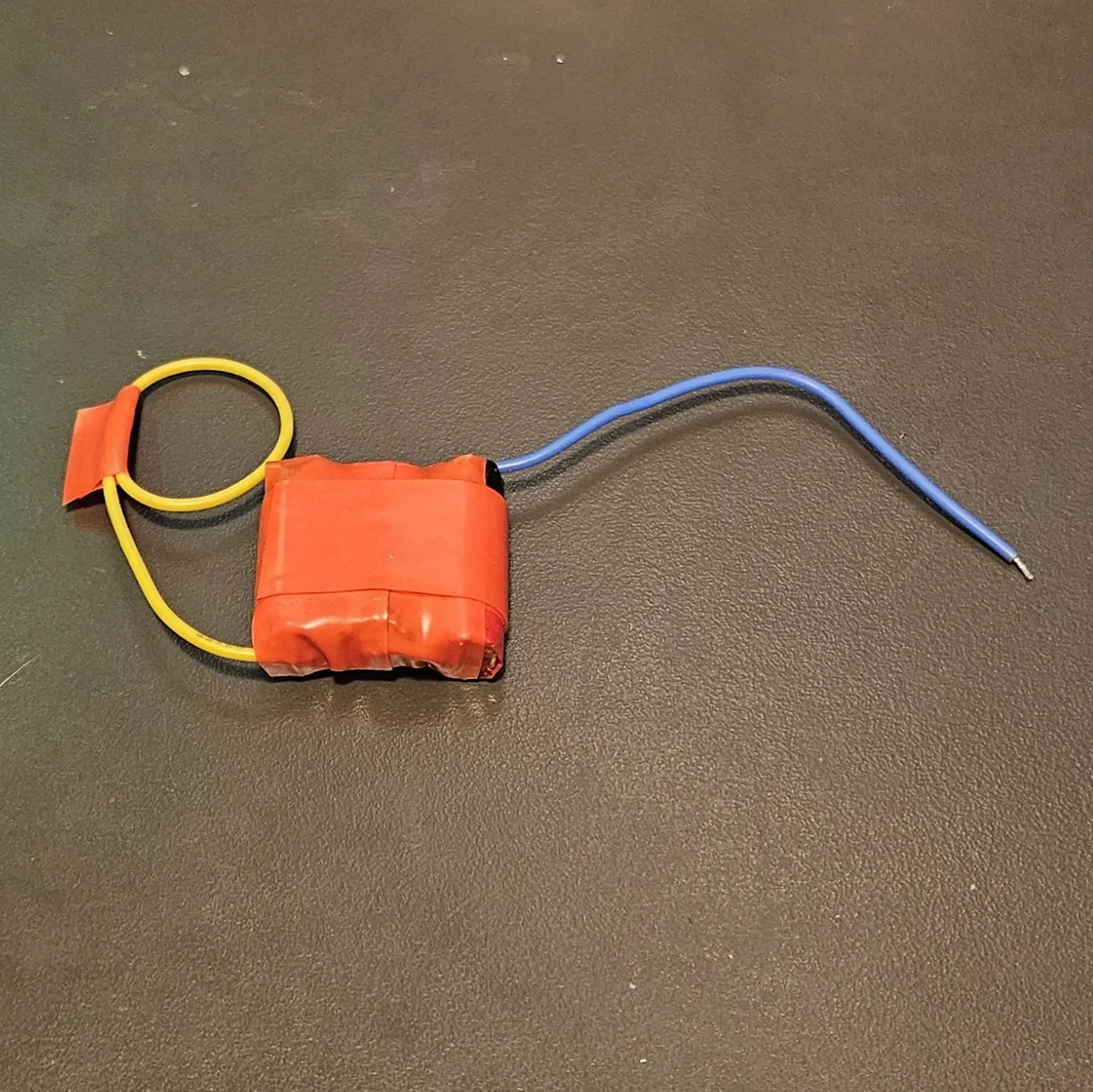 1× Power source - at least two vape cells in series (7.4V; three gives you 11.1V), or a 9V battery
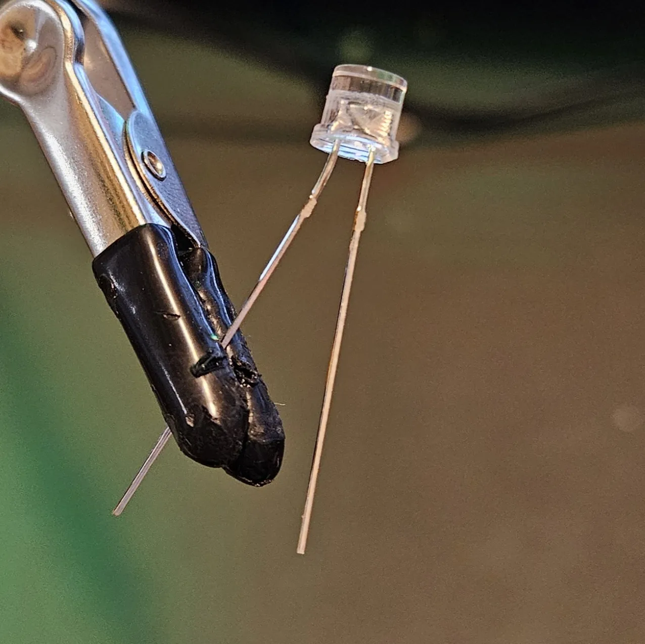 1× LED + a series resistor (~1K–10K) as a power indicator. Spot it: the longer leg is + (anode), and the flat spot on the rim marks the negative side
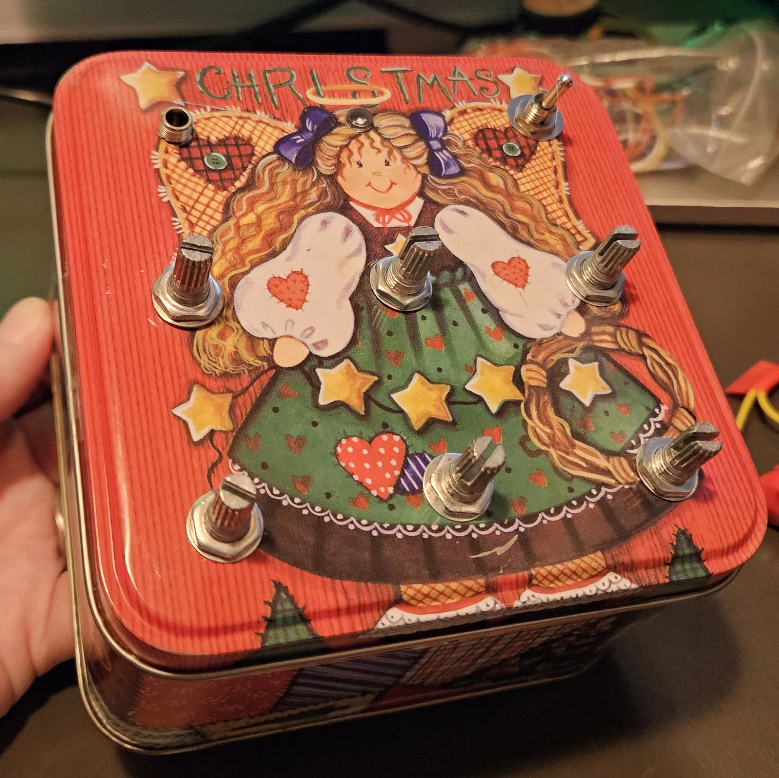 1× Enclosure preferably grounded, if not, then copper tape for grounding
- Solid-core hookup wire, soldering iron, cutters, multimeter
Quick reference - the whole build on one card
Pinout plus every connection at a glance. The steps below walk through it slowly; this is the bench card.
“A” = input, “Y” = output. Notch marks pin 1. Keep the chip label-up and this map reads exactly as you see it — no mirroring, no mental flipping.
Power (first)
- Pin 14 → V+ (3–15V; vape pack ideal)
- Pin 7 → ground
- 0.1 µF across pin 14 ↔ pin 7
- Every unused input → ground
One voice (repeat per inverter)
- Output → input via R (1M pot + 1K series) - pitch
- Input → ground via C (0.1µF low … 0.001µF high; 1µF = LFO)
- Output → to mixer
The six voices - in / out
- V1 → in 1 / out 2
- V2 → in 3 / out 4
- V3 → in 5 / out 6
- V4 → in 9 / out 8 (right side flips!)
- V5 → in 11 / out 10
- V6 → in 13 / out 12
Mix → out
- Each output → 10K → shared mix bus
- Mix bus → output
- Mix bus → 10µF (+ to bus) → jack / LM386 → ground
Step 1 Presolder everything, then populate the panel
Do this before the chip ever comes out of its bag. Every joint you make on a loose part at the bench is a joint you don't have to make later, one-handed, inside a tin, next to five wires that are already in the way.
Tin every leg and every wire end first. A tinned lug and a tinned wire join with a single touch of the iron — no third hand, no holding a wire steady while you chase it with solder.
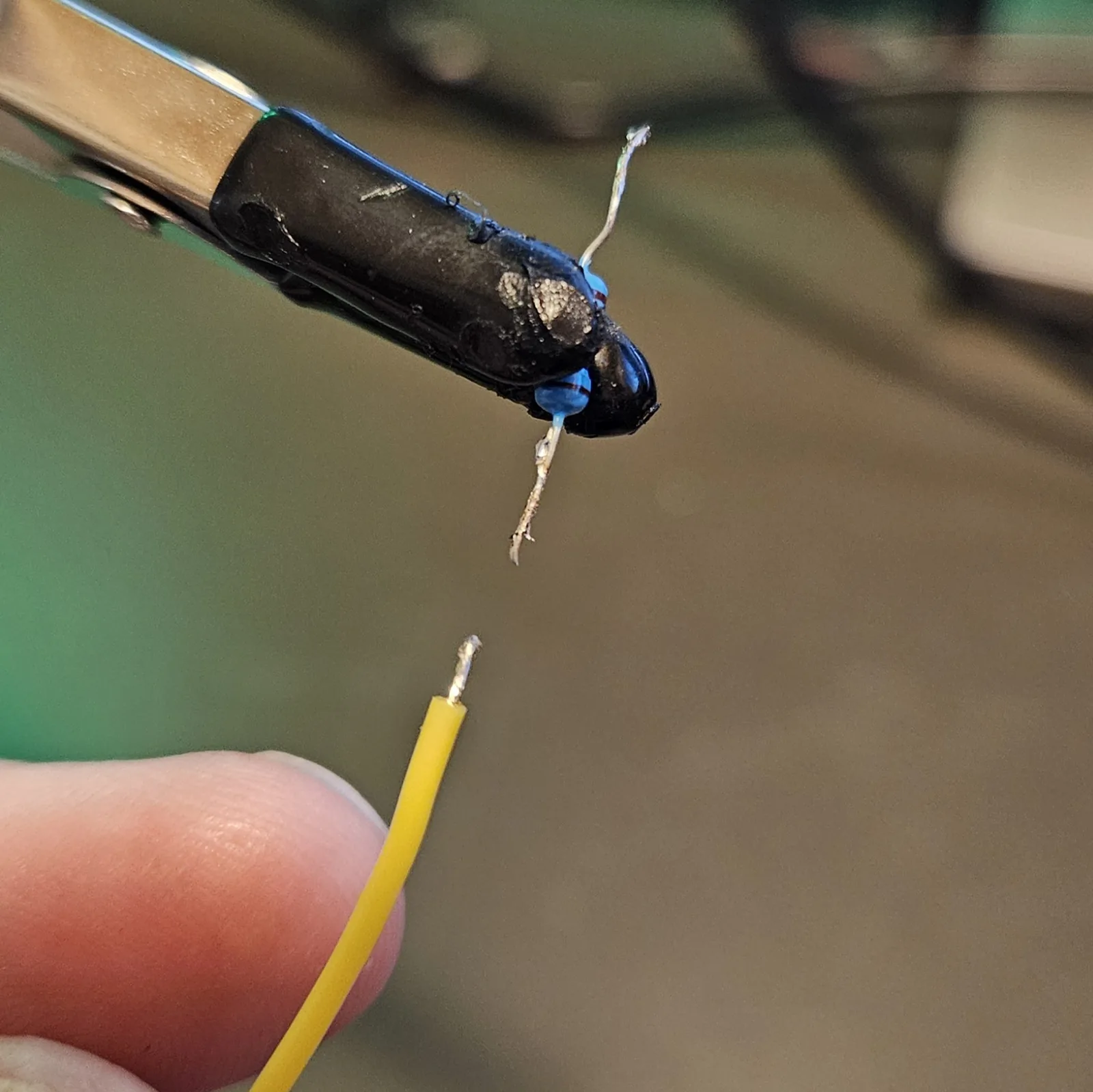
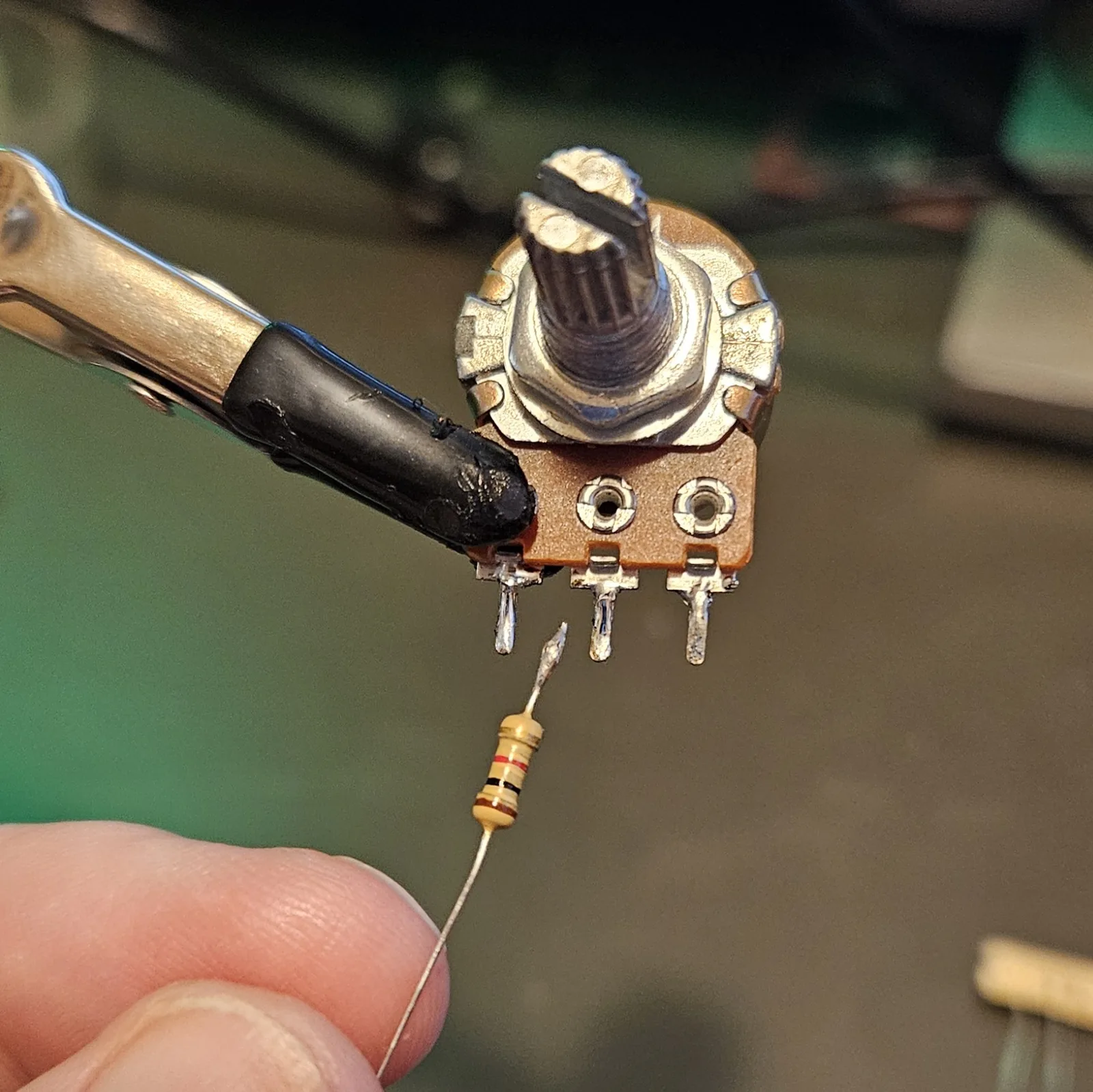
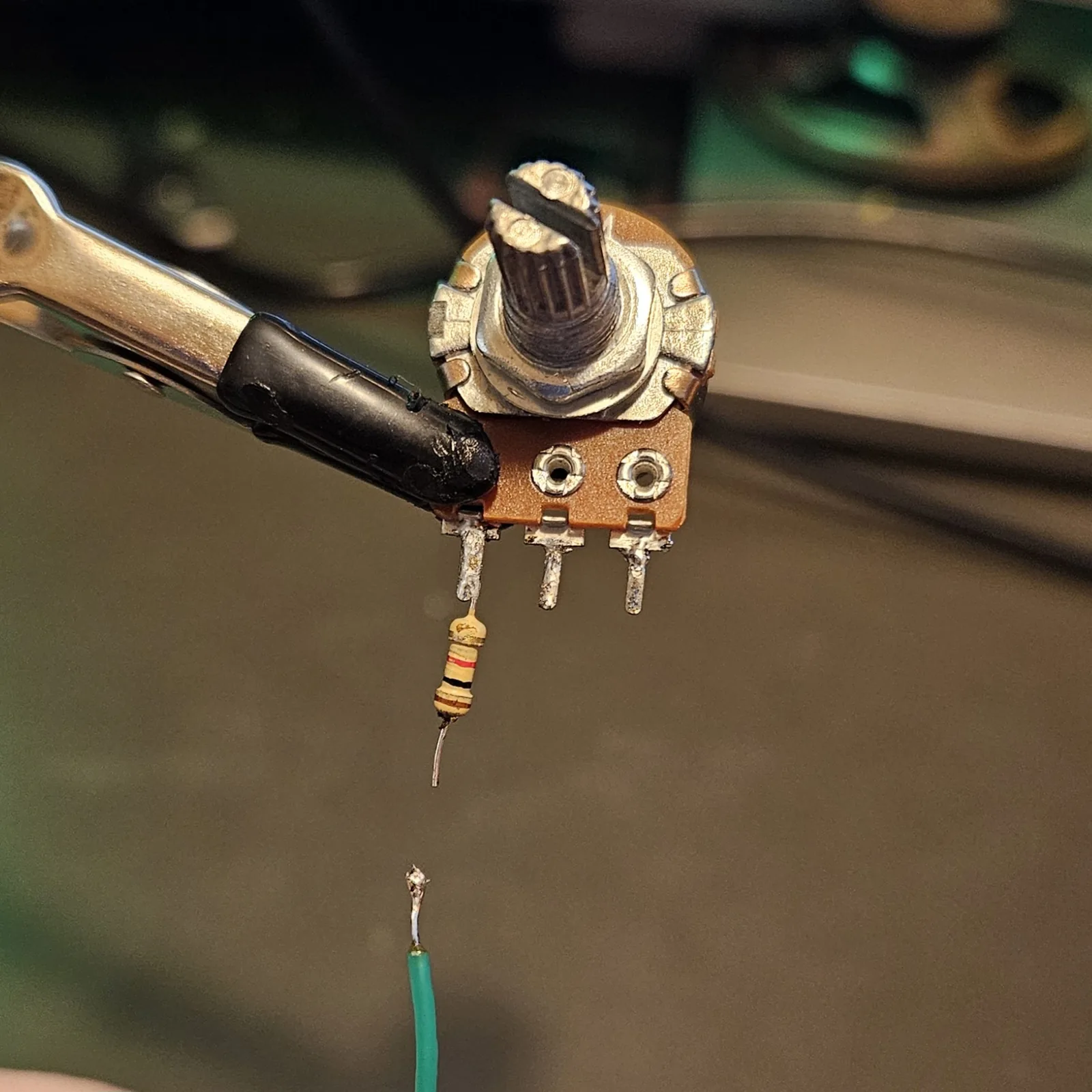
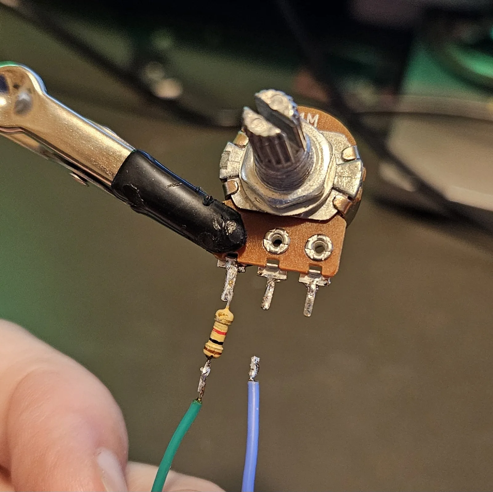
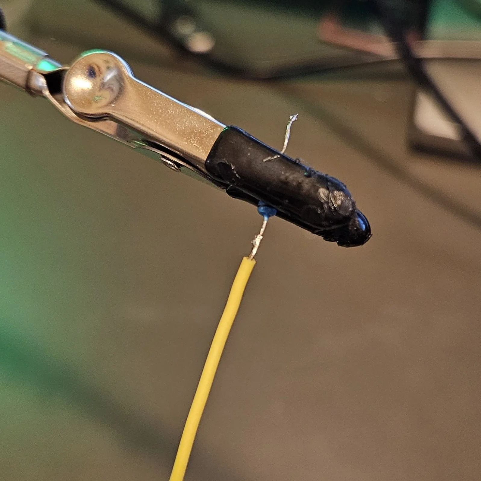
Pots need one more thing before they go in: snap the anti-rotation tab off unless your enclosure has the matching hole for it. Same move as in the ISD1820 build — grip it with needle-nose pliers and it breaks away cleanly.
Now drill the panel and mount everything: six pots, the LED, the toggle and the output jack. There is a 1:1 drilling template for the 4.5″ tin further down if you want the hole positions done for you.
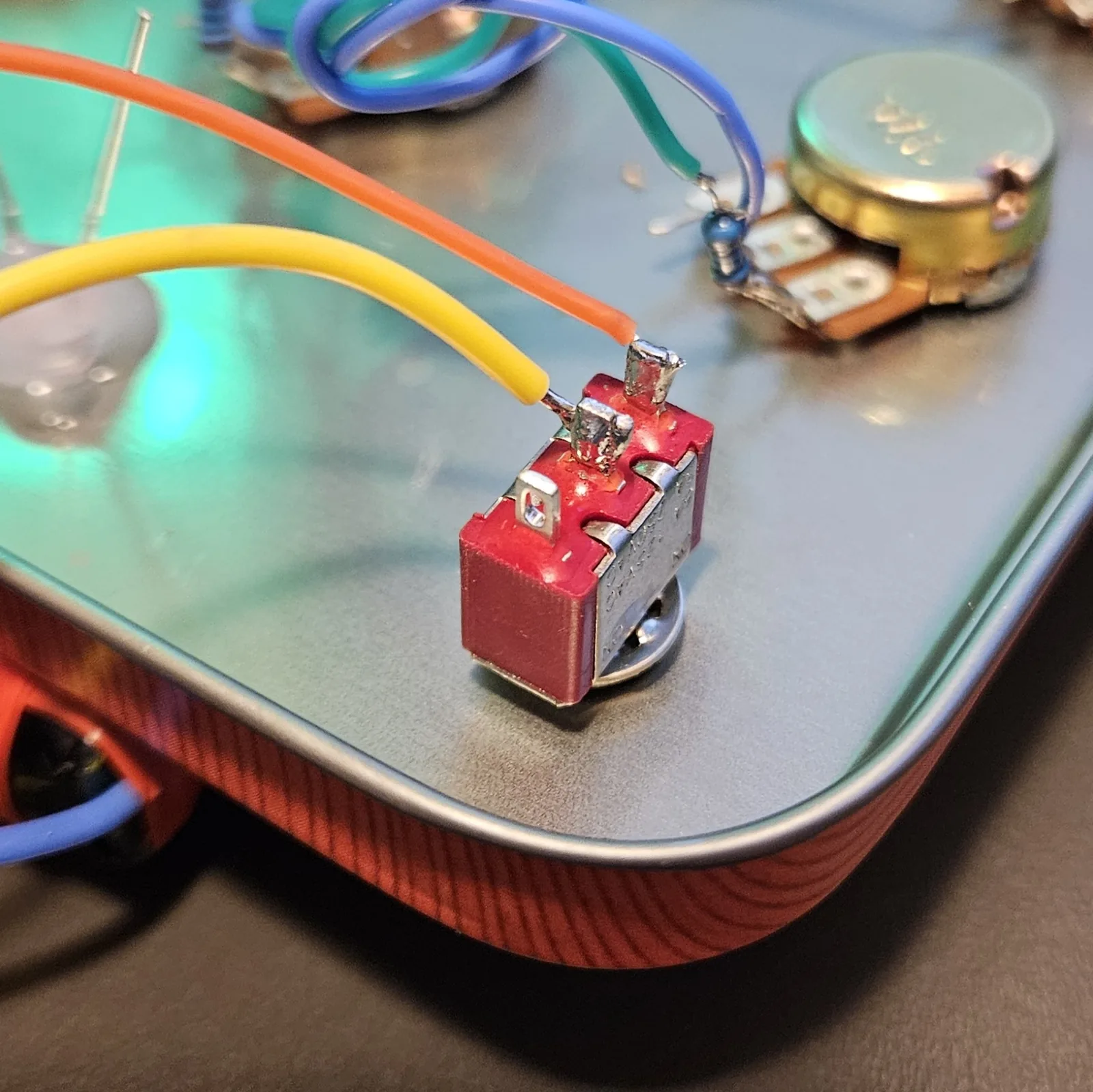
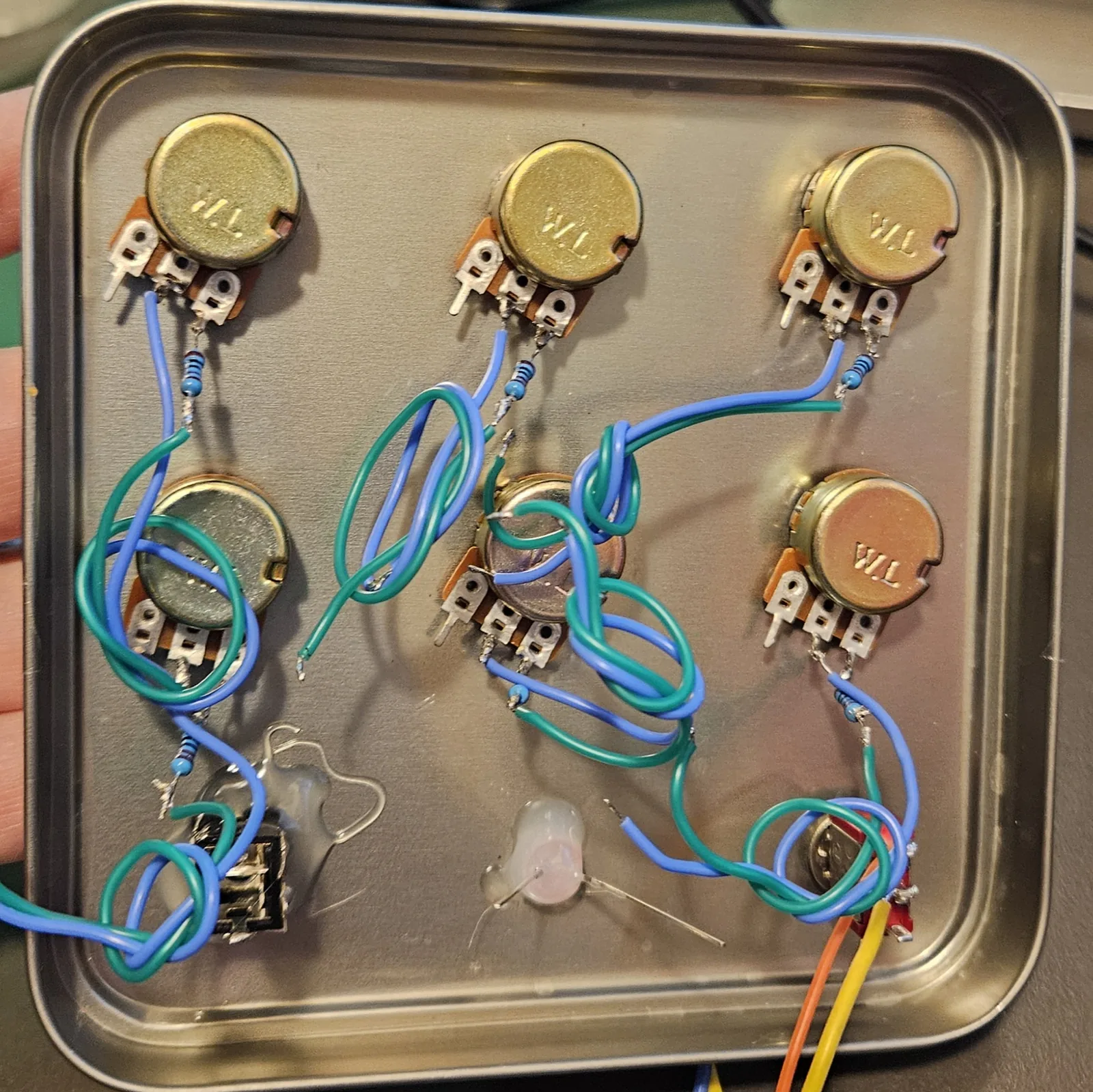
This is the order that saves the most grief. By the time the CD40106 comes out, the enclosure is a finished harness waiting for it, and every remaining joint is on the chip itself.
Step 2 Flatten the legs — and leave it label-up
Bend all fourteen legs out flat, so they splay sideways instead of pointing down. Those flattened legs are your tie points; everything solders straight onto them.
Do not flip the chip over. Plenty of dead-bug guides tell you to glue it belly-up, and that is where people get lost: flipping the package mirrors the pinout, so every pin lands on the opposite side from the map you're reading. Leave it label-up, notch where you can see it, and the pinout above matches the chip in front of you exactly.
I keep it label-up right through mapping the pinout, wiring the decoupling cap, and soldering the first pins. There is no point in the build where flipping it makes anything easier.
Step 3 Power rails - and the CMOS rule
Run a V+ bus and a ground bus, hook up the two power pins, and drop the decoupling cap across the chip. Then the one rule that trips everybody up: every inverter input you're not using gets tied to ground. Building three voices out of six? Tie the other three inputs (pins for 4A, 5A, 6A, whichever you skip) straight to ground. Leave the unused outputs alone - it's only floating inputs that misbehave.
| Connect | To | Why |
|---|---|---|
| Pin 14 | V+ | Supply positive (VDD) |
| Pin 7 | Ground | Supply negative (VSS) |
| 0.1 µF | Pin 14 → Pin 7 | Decoupling, right at the chip |
| Every unused input | Ground | No floating CMOS inputs - ever |
Step 4 Build one voice
Here's the whole oscillator, on inverter 1. Resistor from the output (pin 2) back to the input (pin 1); cap from that input to ground; the output is your signal. Make the resistor a 1M pot (plus a ~1K series resistor) and you've got a pitch knob. Get this one squeaking before you build the rest.
| Connect | To | Part |
|---|---|---|
| Pin 2 (out) | Pin 1 (in) | Pitch = 1M pot + 1K series |
| Pin 1 (in) | Ground | Range cap (e.g. 0.1 µF) |
| Pin 2 (out) | → to mixer (Step 5) | Signal tap |
Step 5 Add the rest of the hive
Every voice is the same three connections - just on a different inverter. Here are all six input/output pairs. Give each a different cap for a wide spread, or the same cap with different pots for a tight, beating cluster. You don't have to build all six; two or three already sound huge.
| Voice | Input (A) | Output (Y) | Suggested cap |
|---|---|---|---|
| 1 | Pin 1 | Pin 2 | 0.1 µF - low growl |
| 2 | Pin 3 | Pin 4 | 0.1 µF |
| 3 | Pin 5 | Pin 6 | 0.01 µF - mid |
| 4 | Pin 9 | Pin 8 | 0.01 µF |
| 5 | Pin 11 | Pin 10 | 0.001 µF - high whistle |
| 6 | Pin 13 | Pin 12 | 1 µF - slow LFO / clicks |
Note the right side flips: on inverters 4–6 the output is the lower-numbered pin. Watch which is A and which is Y.
Step 6 Mix them down
You can't just tie the outputs together - they'd fight. Give each voice a ~10K resistor into a shared mix bus node; that lets them blend politely. Then run the bus straight to the output stage - there is no volume pot on this build, the level is set by the amp you plug into.
Each voice also gets a 1 µF mixing capacitor, and the order matters: voice output → 10K resistor → cap → mix bus. Resistor first, cap second. Six voices, six resistors, six caps.
Use non-polarised (NP / bipolar) caps here. Audio swings both directions, so a part that doesn't care which way round it sits is the sane default.
Bench note - untested variation tap to expand / collapse
On this particular build I'm using ordinary polarised 1 µF electrolytics instead of NP, purely because I have a pile of them and I want to hear what happens. I have not built it this way before.
Don't copy that part yet. Wire NP caps and you're on known ground. If the polarised ones turn out fine I'll say so here; if they don't, this note becomes the warning.
| Connect | To | Part |
|---|---|---|
| Each voice output | 10K resistor | then the cap - resistor first |
| 10K resistor | Mix bus | via a 1 µF NP cap |
| Mix bus | Output stage (Step 7) | no volume pot on this build |
Want per-voice level or on/off? Give each voice its own small pot or toggle before the 10K instead. That's the difference between a fixed drone and a playable one.
Step 7 Get it out of the box
Unlike the 555, the 40106's little logic outputs can't shove a speaker around on their own - straight into 8 Ω you'll get a whisper. Pick your output to match how loud you need it:
| Option | How | Result |
|---|---|---|
| LM386 amp | 10 µF → LM386 input → speaker | Actually loud — it's the next chip in your pile (the Dead-Bug Hornet) |
| Line / jack out | 10 µF → 1K series → jack tip; sleeve to ground | Into an amp or pedal - let them do the work |
Step 8 Power up
Wire your SPST toggle in the V+ line, flip it, and start sweeping pitch knobs. Each voice comes in as its own tone; together they beat, throb, and grind. Swapping caps mid-build is the fastest way to find the range you like.
Voltage note tap to expand / collapse
The CD40106 is CMOS and runs happily anywhere from about 3V to 15V. More volts shifts the pitches up and stiffens the output a touch. At least two vape cells in series (7.4V - three gives you 11.1V) or a 9V battery.
Step 9 If it won't sing
- A voice is dead silent? Double-check its feedback resistor really goes output→input, and the cap goes input→ground. Easy to swap A and Y on the right-hand side (pins 8–13), where the output is the lower pin number.
- Whole chip buzzy or hot? A floating input. Hunt down any unused inverter input and tie it to ground.
- No sound at all? Confirm pin 14 at V+ and pin 7 at ground, and that you didn't skip the 0.1 µF decoupling cap.
- Barely audible? That's the raw output into a speaker - expected. Add the LM386, or go into an amp (Step 6).
- A pot does nothing at one end? The series resistor doing its job. Nothing at all? You're on the wrong two lugs - use the wiper + one end.
The 6-pot template isn't up for download yet — measure from the dimensions above for now. (The tin template linked earlier is a different size; don't print that one for this panel.)
Going further: make them misbehave
Six independent voices is just the start. The fun is getting them to talk to each other:
- Cross-modulation. Run one voice's output through a resistor (~100K) into another voice's input node. Now one oscillator warps the other's pitch - growls, sidebands, and gnarly FM textures. Try a slow voice modulating a fast one.
- Built-in LFO. Give one voice a big cap (1 µF+) so it ticks below hearing, and patch it into the others' inputs - instant tremolo, sirens, and rhythmic pulsing.
- Body contacts. Bring an inverter's input out to two bolts. Bridge them with a wet finger and your skin's resistance bends the pitch.
- Feed the series. A 40106 voice makes a perfect clock for the next builds - run one into a CD4024 to divide it into sub-octaves and stepped melodies, or into a CD4046's CV input to sweep a whole other oscillator. That's where these three chips become one instrument.
- Gate it. Want the drones to pulse instead of hold? The Dead-Bug Cicada is this same idea on a CD4093, whose voices have enable inputs - let a slow Cicada voice switch the Hive on and off for rhythm.
Build one voice, get it squeaking, then keep going down the row. By voice six you'll understand exactly why people hoard these chips. Show me what you make.
The 40106 oscillator is folk knowledge of the DIY-synth / Lunetta world - the same building block behind Ray Wilson's MFOS Weird Sound Generator and countless noise boxes. This write-up, wiring, and words are my own. Build it, bend it, make it yours.