Four Modes, One Chip
The ISD1820 breakout nobody cares about · By Onion Madder · Mess O' Pedals
The ISD1820 is the ubiquitous blue voice-recorder module out of every talking greeting card, and near enough every tutorial wires it for three things: record, play once, play looping. But the chip has a fourth mode sitting right there on a pin nobody connects - feed-through, which sends the mic straight to the speaker in real time. Wire that one extra pin and your sampler is also a megaphone.
This is the breakout I built for my talk-box, and the feed-through is what takes this project from "noise box for one" to "annoy the neighbors for fun and profit".
⚠ Before you start tap to expand / collapse
Hot iron, obviously. Ventilate, don't breathe the flux smoke, park it in its stand every time.
Feed-through is live audio into a speaker. Mic and speaker in the same box is a feedback loop waiting to happen - point the speaker away from the mic, and start with the volume down before you go hunting for the squeal.
Mind your supply. The ISD1820 module is a 3–5V part. This is the one build in my series that does not want a big series pack - see Step 8.
What feed-through actually is
Straight from the datasheet: pull the FT pin high and the signal between MIC and MIC_REF runs through the chip's AGC, filter and speaker drivers and out of SP+ / SP−. It is not a recording, it is not a playback - it is the chip acting as a live amplifier, using the exact same audio chain playback uses. No extra amp, no extra parts. One wire.
Two things worth knowing about that pin before you wire it:
- FT has a weak pull-down to Vss, so it idles LOW on its own. You don't need an external pull-down resistor, and leaving it unconnected is perfectly safe - that's just “feed-through off.”
- Feed-through only engages if REC, PLAYE and PLAYL are all LOW at the same time. Pull FT high while any one of those is active and nothing comes out. No damage, no error, no clue - it just silently doesn't work. This is the single most important sentence on this page.
Quick reference - the four modes
Every mode is just a combination of four pins. H = held high, L = low, ↑ = rising edge.

| Mode | REC | PLAYE | PLAYL | FT | Control |
|---|---|---|---|---|---|
| Idle | L | L | L | L | - |
| Record | H | L | L | L | momentary (hold) |
| Sample (one shot) | L | ↑ | L | L | momentary (tap) |
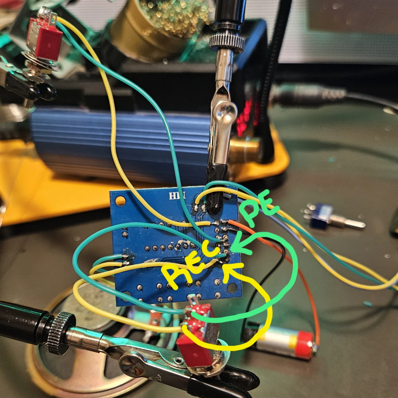
| Loop | P-E pin 2 bridged to REC pin 1 — see Step 6 | its own toggle | |||
| Megaphone | L | L | L | H | its own toggle |
Module pins
- VCC → 3–5V
- GND → ground
- REC → record while high
- P-E (PLAYE) → play once on rising edge
- P-L (PLAYL) → play while high
- FT → feed-through while high
- SP1 connector → speaker
Controls
- Record → momentary to VCC
- Sample → momentary to VCC
- Loop → its own toggle
- Megaphone → its own toggle
- Loop = P-E pin 2 ↔ REC pin 1 (Step 6)
Loop and Megaphone — two switches, not one
Each mode gets its own switch. Megaphone is the straightforward one — a toggle between FT and VCC. Loop is the one that catches people out: it is a jumper between the second pin of P-E and the first pin of REC, which is not on any schematic for this board.
Wiring the two to opposite throws of one centre-off toggle sounds tidy, and it does not work — a shared switch can pull a pin up to VCC, but it cannot bridge two pins to each other, which is what the loop actually needs.
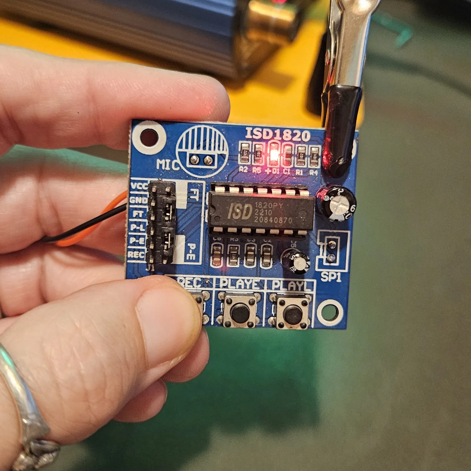
J1 is a 2×6 header. The rows are silkscreened down the left edge — VCC, GND, FT, P-L, P-E, REC — with a second column of pins beside them, plus separate FT and P-E pads to the right of the block. That two-column layout is why "jumper two pins" is the operative instruction here rather than "run a wire to VCC."
What you'll need
New to the parts? Each line notes how to spot it.
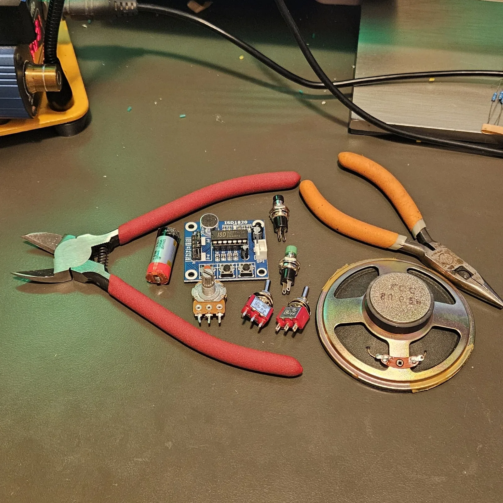
- 1× ISD1820 module - the little blue board with an electret mic and three tactile buttons. Spot it: silkscreen reads ISD1820, and the header pins are labelled VCC / GND / FT / P-L / P-E / REC down one edge - the header shortens the play pins to P-L and P-E even though the buttons say PLAYL and PLAYE
- 2× toggle switches - one for Loop, one for Megaphone. They each get their own switch; a single shared switch does not work
- 2× momentary push buttons - record and sample. Normally-open, so they only connect while pressed
- 1× speaker, 8 Ω - soldered to the pads the SP1 connector came off
- A 3–5V supply - see the note in Step 8. Not a big series pack
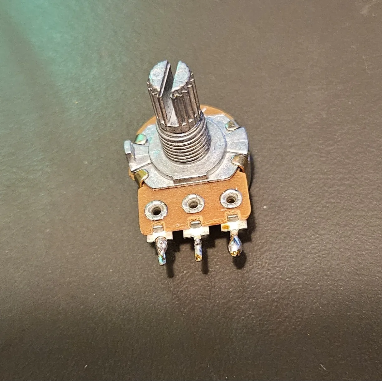
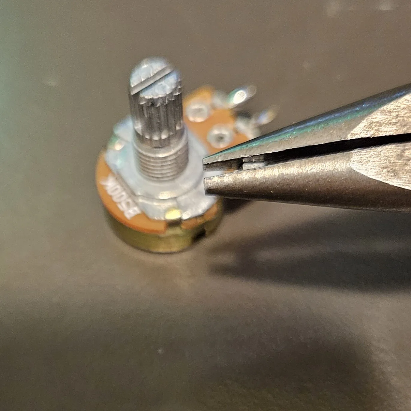
- Optional - 1× 500K potentiometer for the pitch mod (see Pitch control below). Spot it: marked B500K for a linear taper. Most guides say 100K; 500K sweeps a lot further
- Hookup wire, enclosure, soldering iron, cutters, multimeter
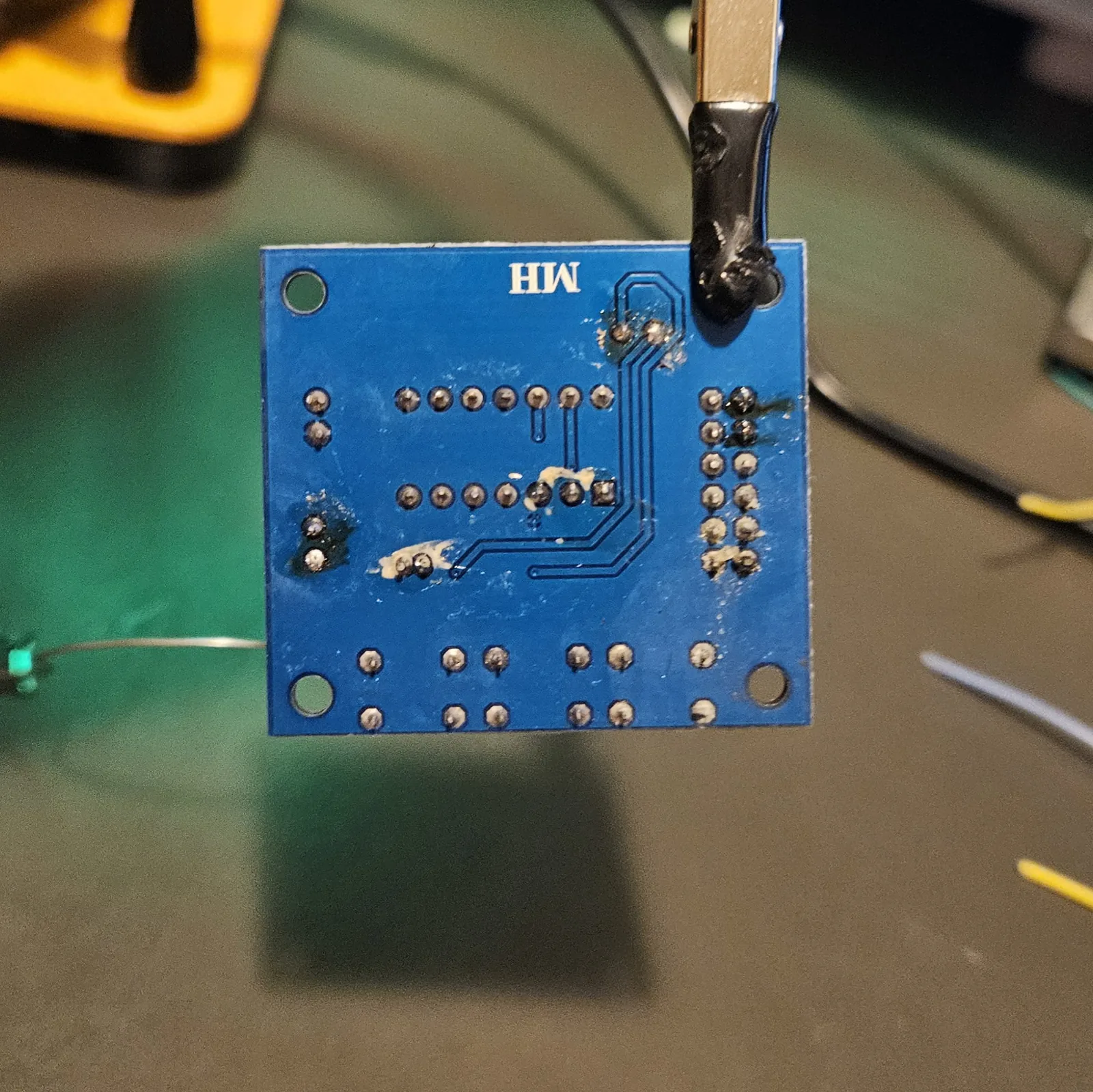
Step 1 Strip the board - the solder-to-desolder trick
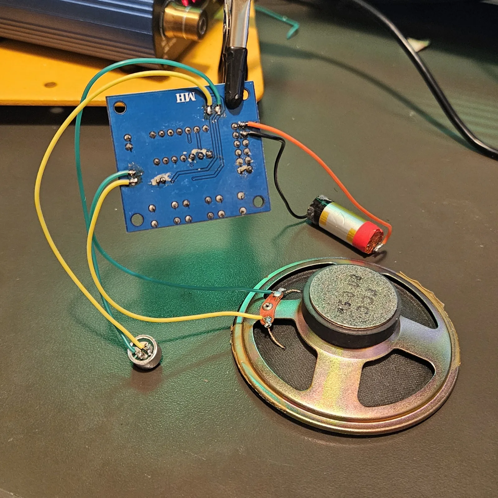
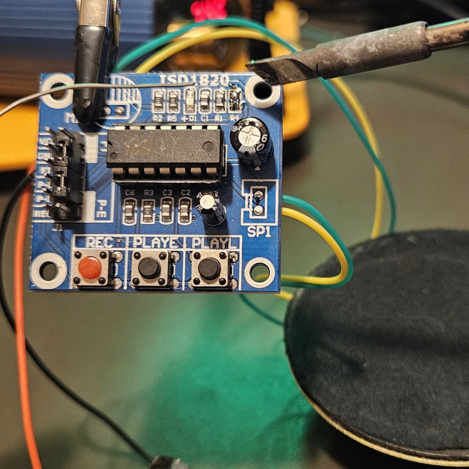
The module ships with a tiny onboard speaker connector and an electret mic soldered in place. Both have to come off so you can run your own speaker and put the mic where you actually want it. This is the first thing you do, and it is where most people fight the board.
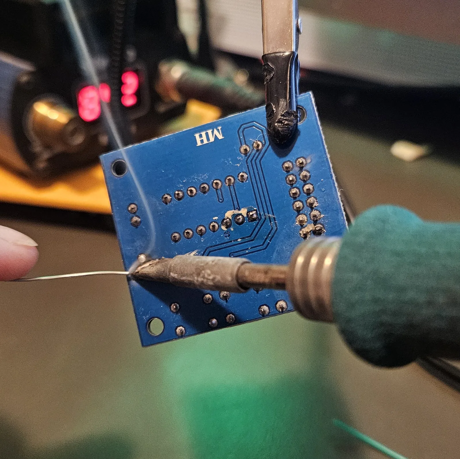
Do not try to suck the joint dry. The trick is the opposite of what it sounds like: add more solder. Fresh solder carries fresh flux, and that flux is what makes the old joint flow again. Pile a good blob across the pads, keep the iron moving between them so the whole thing stays molten, and the component essentially falls out. No braid, no pump, no lifted pads, no heat-soaking a part until it dies.
The other half of the trick is helping hands. Clip the board so both of your hands are free - one for the iron, one for the solder - because this only works while the joint is still liquid and you have about a second to lift the part clear.
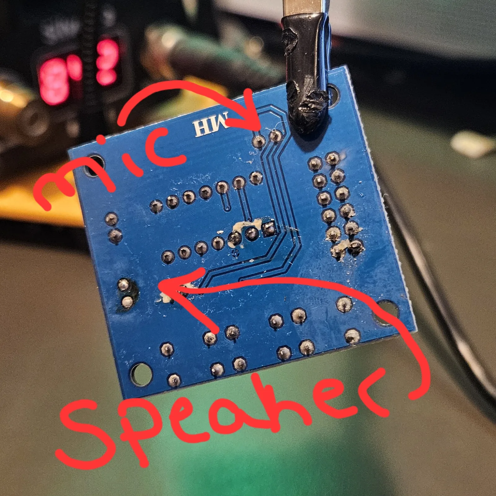
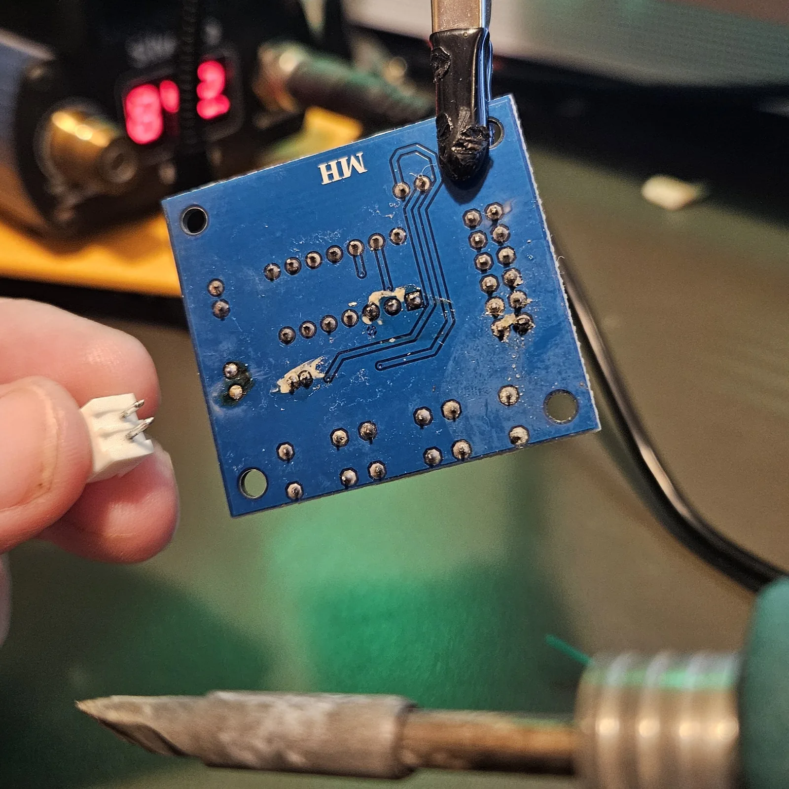
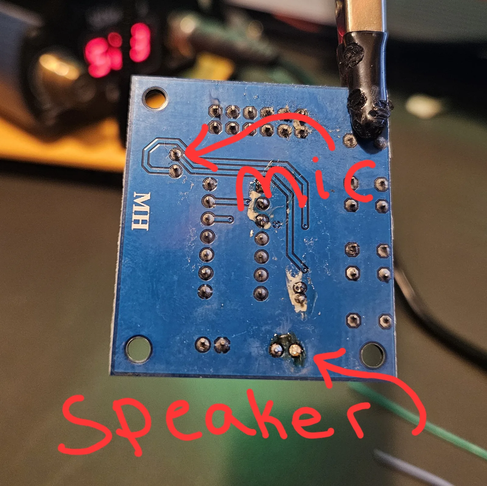
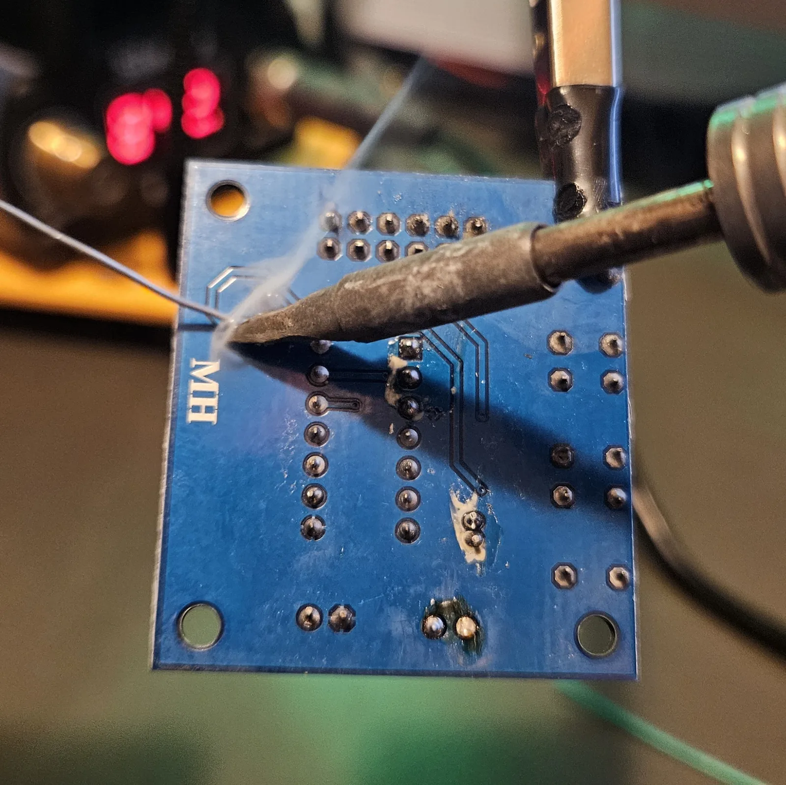
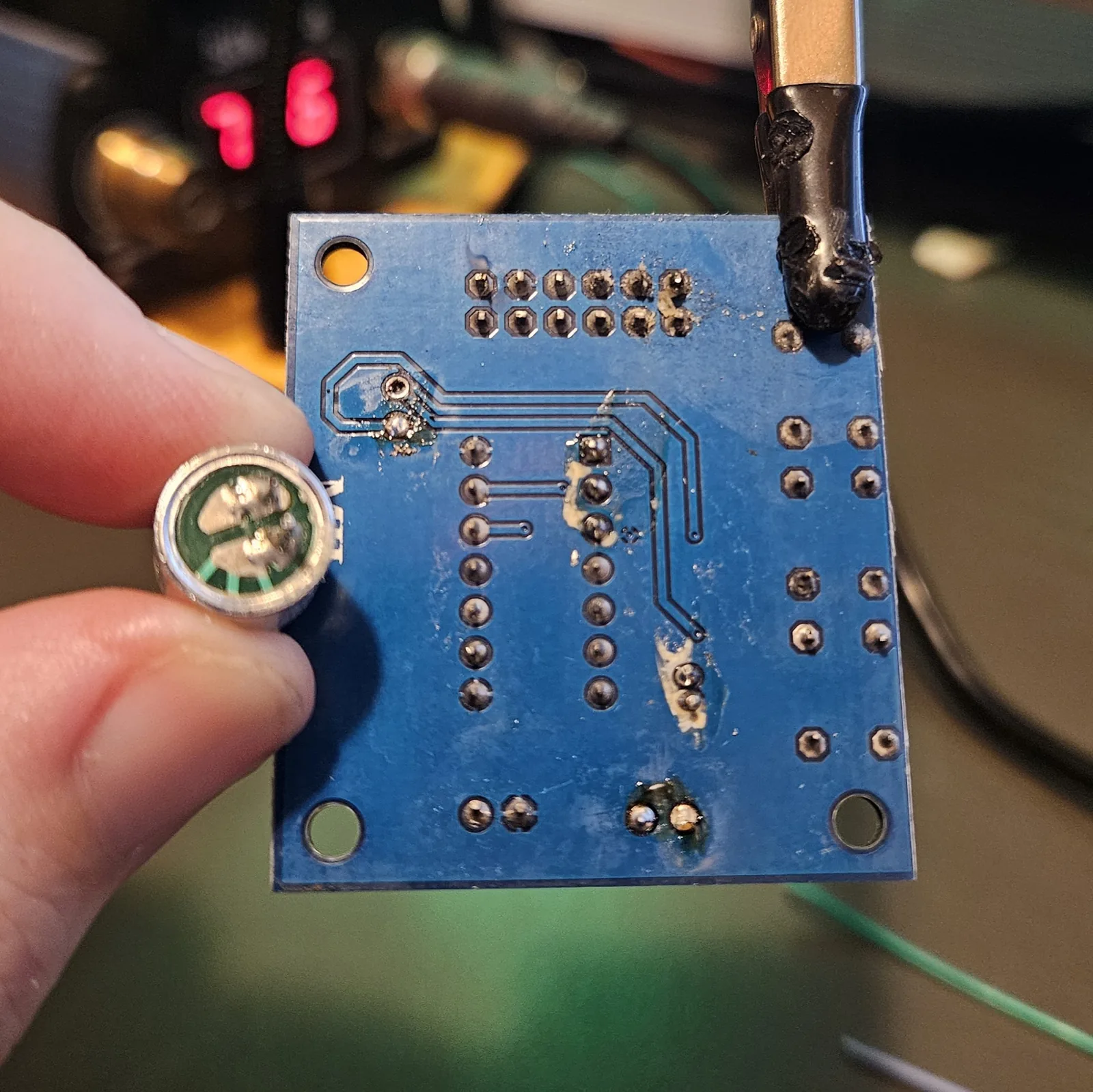
Save both parts. That electret is the mic your megaphone mode listens through, so it is going straight back on a pair of wires - just somewhere you choose, rather than flat against the board. When you re-attach it, make sure its ground leg is properly grounded. An ungrounded mic is the difference between a megaphone and a howling mess - see Step 5.
Step 2 Power it up bare first
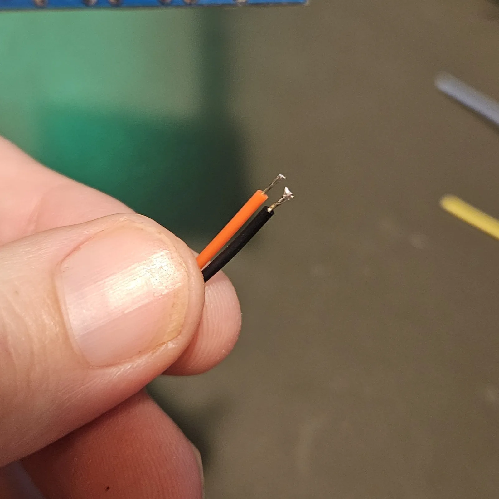
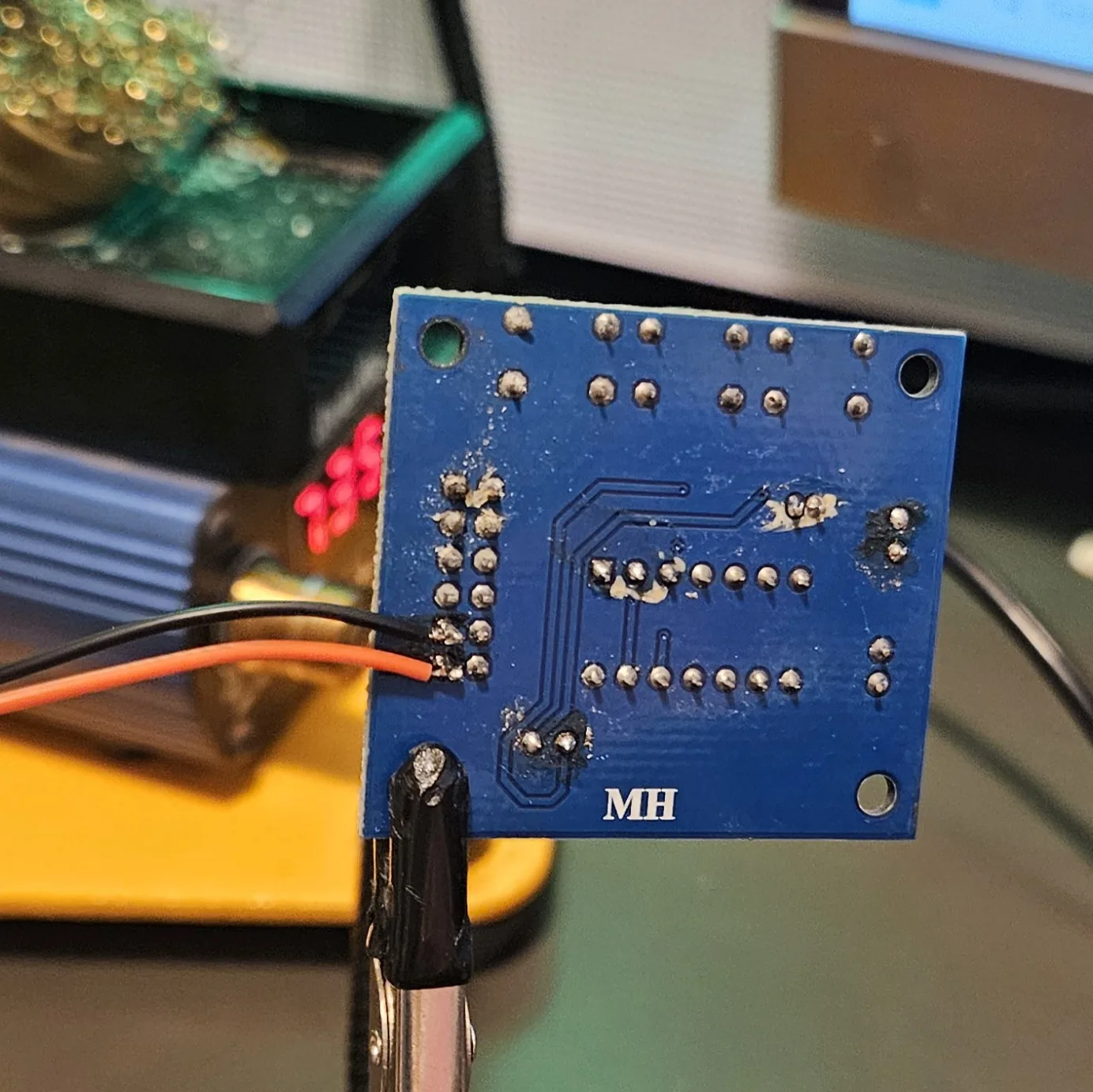
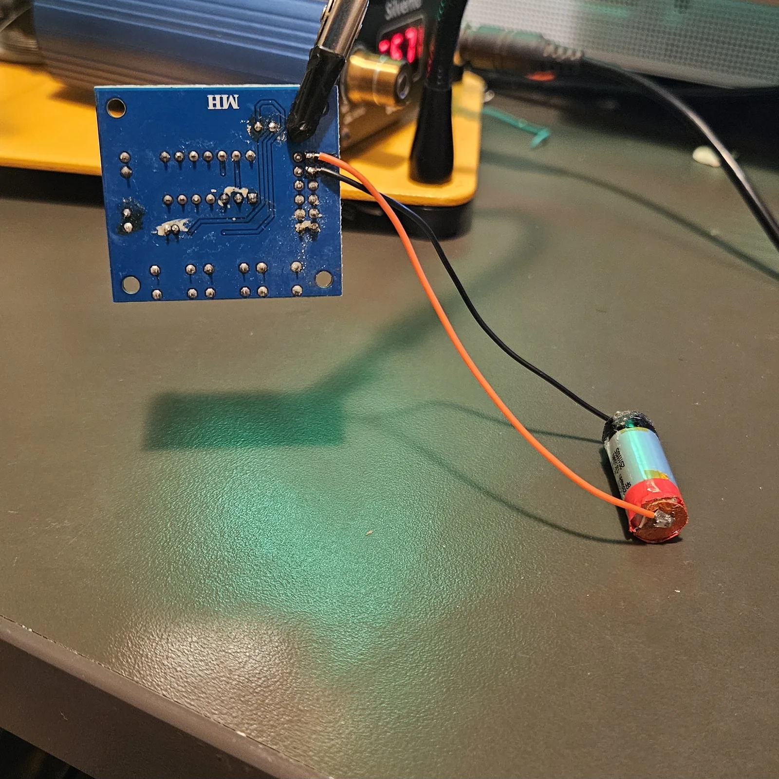
Before you wire a single control, give the module VCC and GND and a speaker, and use its onboard buttons to record and play something. The board ships with tactile buttons for REC / PLAYE / PLAYL precisely so you can prove it works before you commit to a panel. If it won't record now, no amount of switch wiring will fix it.
Step 3 Record - momentary to VCC
REC records for as long as it is held high. That is a hold-to-record button, not a tap-to-start one, so a normally-open momentary from REC to VCC is all it takes. Let go and the recording ends there.
| Connect | To | Part |
|---|---|---|
| REC | VCC | momentary push button |
Step 4 Sample - momentary to VCC
PLAYE is edge triggered: it fires on the rising edge and plays the whole message through, whether or not you keep holding it. That is your one-shot sample button - tap and it goes.
| Connect | To | Part |
|---|---|---|
| PLAYE | VCC | momentary push button |
Step 5 Megaphone — its own toggle
The megaphone side is the simple one. A toggle between FT and VCC, and that is the whole connection. Flip it and the mic feeds the speaker live.
| Connect | To | Part |
|---|---|---|
| One lug | FT | its own toggle |
| Other lug | VCC |
FT idles low on its own, so the switch only ever has to make the connection — there is nothing to pull it back down when you switch off.
⚠ Ground the mic tap to expand / collapse
If the mic isn't grounded you will get mad feedback. Not the ordinary kind you fix by moving the speaker — a genuine howl the moment feed-through goes live.
It bites here specifically because Step 1 takes the electret off the board and puts it on flying leads. On the board its ground was handled for you. On wires, it is yours to get right. Check that ground leg before you go hunting for anything else.
Step 6 Loop — the jumper that isn't in any schematic
This is the one nobody documents. Loop is not P-L pulled up to VCC, and it is not anything you will find on a schematic for this board. It is a bridge between two specific pins on J1:
| Connect | To | Part |
|---|---|---|
| One lug | P-E, second pin | its own toggle |
| Other lug | REC, first pin |
Because J1 is a two-column header, every label on that edge covers two pins — which is the whole reason this is easy to miss. You are not connecting the P-E row to the REC row, you are bridging one specific pin from each, and they sit next to each other on the board. Get the wrong pin of either pair and nothing happens.
I found this by poking at the board and cross-reading other tutorials until something worked — it is not in the datasheet and it is not on any schematic I have seen. If you have only ever seen the three-mode version of this module, this jumper is the difference.
Loop and megaphone still can't both be on at once — the chip needs REC and the play pins low for feed-through, and this jumper drives them. Two separate switches simply means you decide which mode is live, rather than the hardware deciding for you.
Step 7 Speaker
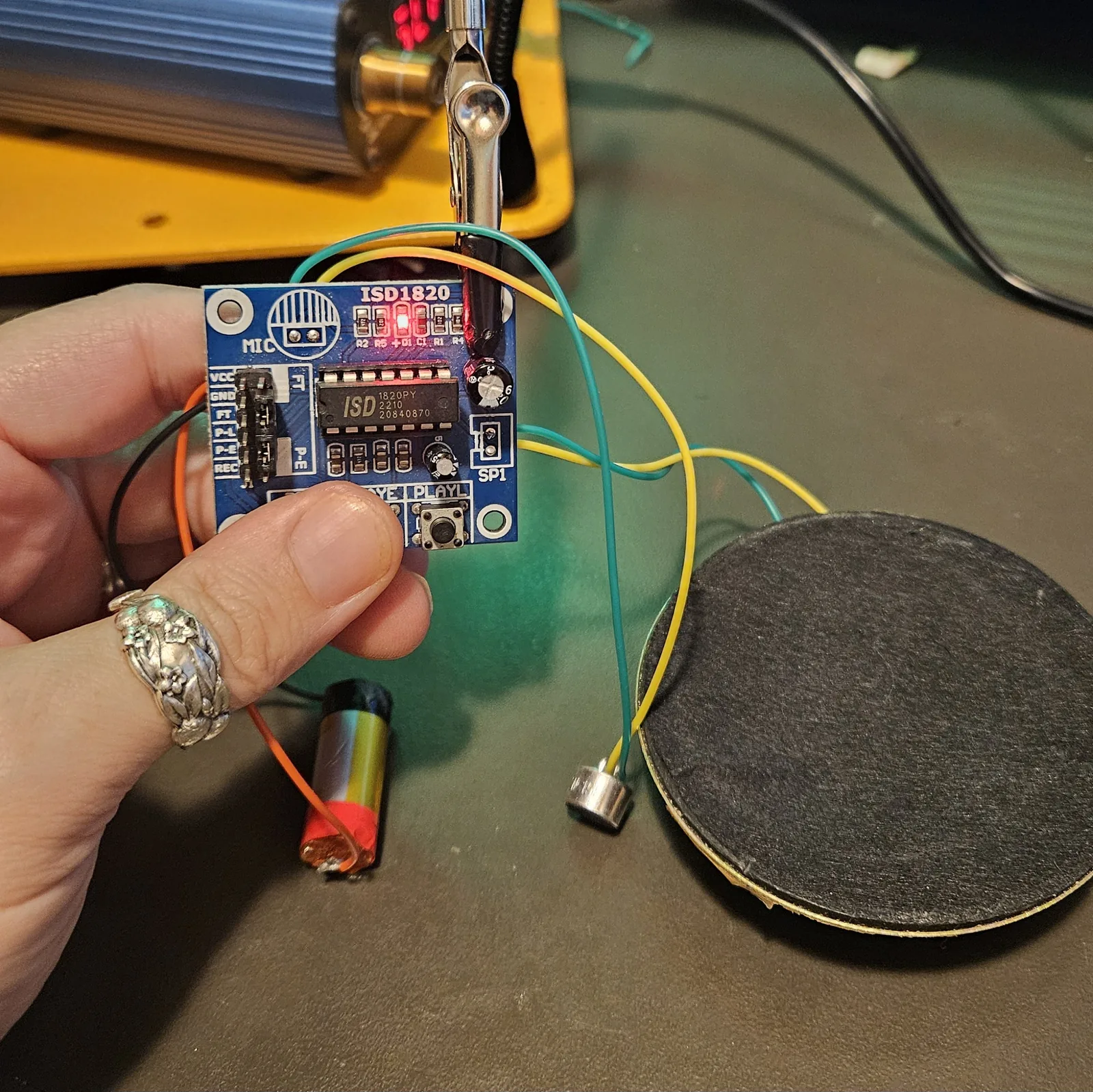
Your speaker goes where the SP1 connector used to be - solder it straight to those two pads. The onboard amp drives it for playback and for feed-through - same chain, so megaphone mode comes out at the same level as your samples with no extra amplifier.
Step 8 Power
The ISD1820 module runs on 3–5V. Do not hand this one a big series pack the way you would a 555 or CMOS build - it is the exception in the series.
A single salvaged lithium cell at ~3.7V lands right in range, which makes the parallel vape pack the correct pack for this build: same 3.7V, double the runtime. That is exactly the low-power case that guide is built for. If you want more hours, add cells in parallel - not in series.
Step 9 If it misbehaves
- Megaphone does nothing? Check the loop side isn't latched on. FT is ignored unless REC, PLAYE and PLAYL are all low. If you wired two separate toggles, this is why - go back to Step 6.
- Megaphone howling? Check the mic ground first. An ungrounded electret feeds back hard the instant FT goes high, and no amount of moving the speaker will fix it. This is the most likely culprit if the noise started after you relocated the mic.
- Still squealing once it's grounded? Ordinary feedback - mic and speaker are hearing each other. Turn it down, move the speaker, or point it away from the mic.
- Records but plays back nothing? Confirm the speaker is on the old SP1 pads, and that REC actually went low again (a stuck button holds it in record).
- Recording cuts off short? That's the chip's fixed message length, set by the onboard sampling resistor - which is also the thing you swap for a pot to get pitch control (see below).
- Nothing at all? Back to Step 2 with the onboard buttons. Prove the board before you blame the panel.
Going further
Pitch control - and which pot to actually use
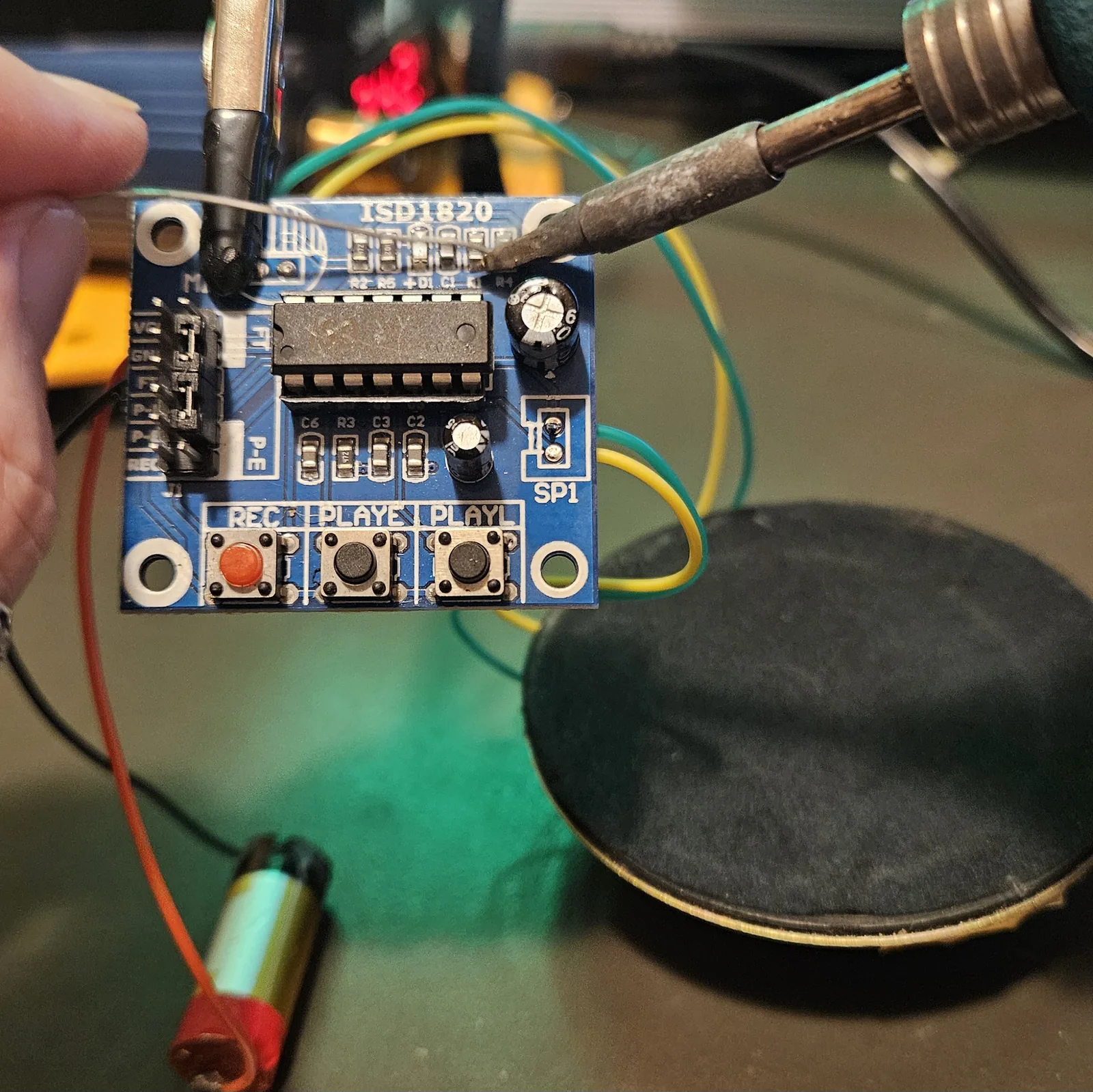
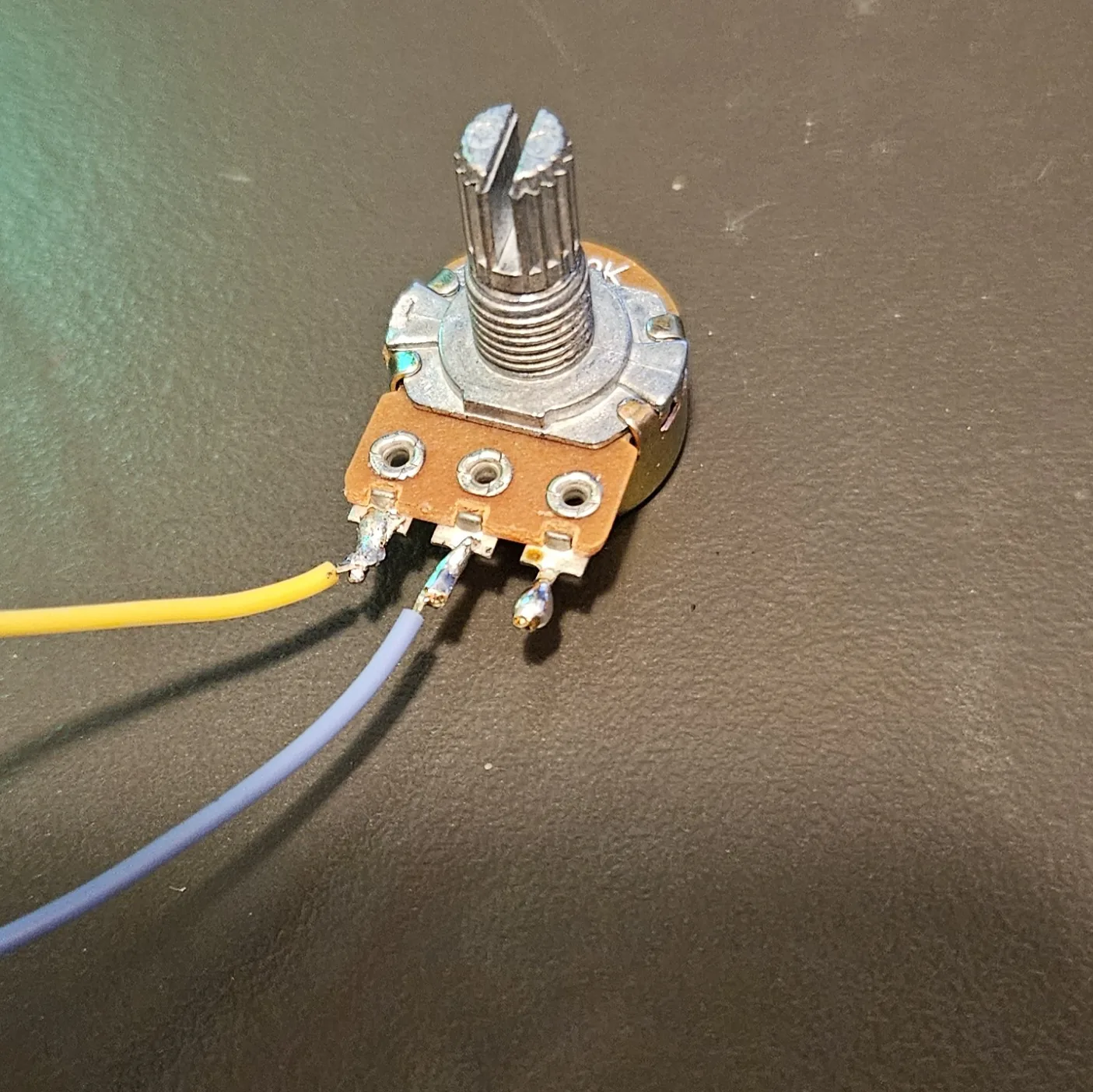
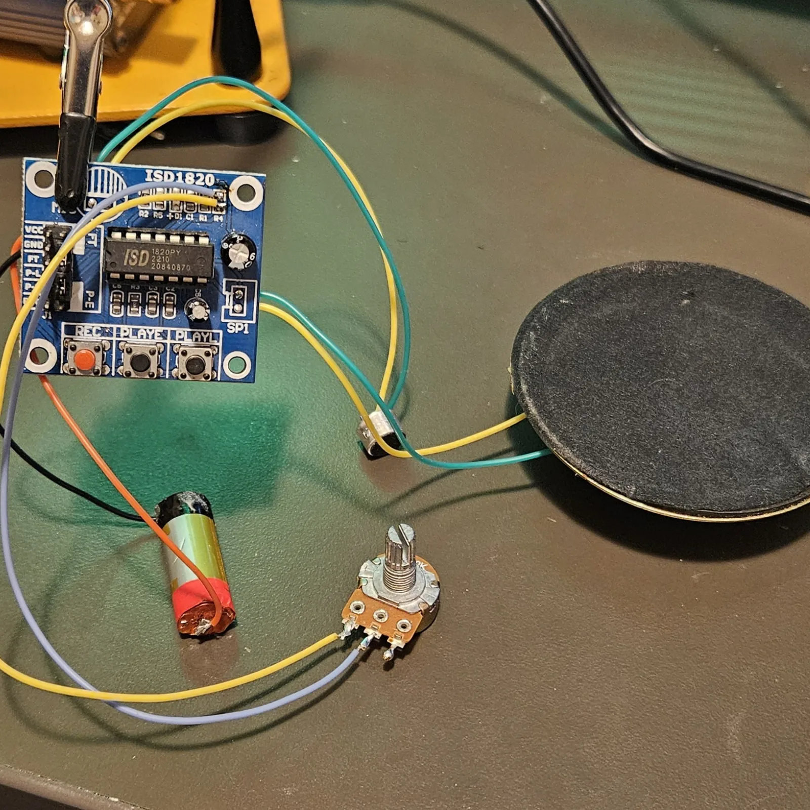
Swap the onboard sampling-frequency resistor R4 for a potentiometer and the playback speed - and with it the pitch - sweeps under your hand. R4 is one of the little surface-mount resistors along the top edge of the board, so the same blob-of-fresh-solder trick from Step 1 lifts it straight off.
Nearly every guide says 100K and stops there. It works - it is also the most timid of the three options:
| Value | What you get | Worth knowing |
|---|---|---|
| 100K | Modest, safe range | What almost every other guide lists |
| 500K | Much wider sweep | My pick - the sweet spot for range without weirdness |
| 1M | The really deep groans | Buyer beware: at the far end it plays so slow and so quiet that people assume the box is broken |
That 1M caveat isn't a fault - it's the range simply running out past the point of being useful. If you're building one for somebody else, fit the 500K or warn them, otherwise the first thing you'll hear back is that it stopped working.
Darren Shaw's walkthrough of the R4 swap is mirrored here: Modifying an ISD1820 into a Lo-Fi Sampler.
Other directions
- Put it in something. Same chip is the heart of Loopy Louie (in a Gooey Louie head) and Bent Brooks (in a decorated skull).
- Line out. Tap one SP1 pad through a coupling cap and a level pot for a jack, so the box can feed a pedal chain instead of only its own speaker.
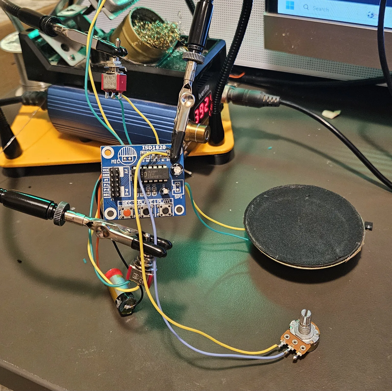
All together
Written by Onion Madder. Feed-through pin behaviour per the ISD1820 datasheet (module user guide); the four-mode panel wiring is worked out from my own builds. Build it, bend it, make it yours.