Dead-Bug Screamer
A point-to-point NE556 noise box · By Onion Madder · Mess O' Pedals
One chip, a fistful of parts, zero perfboard. The Atari Punk Console is the perfect solder-it-yourself noise box: it makes a racket the second you power it up, and you can build the whole thing dead-bug style: the chip's legs are flattened, every part soldered straight to its legs. No breadboard, no PCB, no etching. Just you, a hot soldering iron, and a spider made of wires.
This is the exact build behind my Dead-Bug Screamer project - the one that fired up on the first try, living in a clear card box off a playingcarddecks.com order and running on a battery pack made from dead vapes.
⚠ Before you start tap to expand / collapse
Hot iron, obviously. A soldering iron is 350°C of don't-grab-that. Work in a ventilated spot, don't breathe the flux smoke, and park the iron in its stand every single time you set it down.
Mind the polarity. The electrolytic output cap and your power source both care which way round they go. Backwards electrolytics can bulge or pop - double-check the stripe (that's the minus leg) before you commit.
If you power it from a salvaged lithium pack like I do, all the usual cell cautions apply - don't short it, don't puncture it, charge it right. That's its own guide: Do You Want to Survive the Vapocalypse?
It gets loud and shrill. The APC can hit piercing high frequencies. Be kind to your ears (and anyone sleeping in the next room) before you crank it.
How it works, in one breath
The NE556 is just two 555 timers in one 14-pin chip. The Atari Punk Console (Forrest Mims called it the “Stepped Tone Generator”) wires them nose-to-tail: timer A free-runs as an oscillator, and its output triggers timer B, a one-shot that fires a single pulse per cycle. A fast oscillator re-triggering a slower one-shot doesn't give you a clean tone - it gives you that gnarly, gated, stepped square-wave squawk the circuit is loved for. One knob sets the pitch, the other sets the pulse width (the “shape”), and between them lives a surprising amount of chaos.
What you'll need
New to the parts? Each line notes how to spot it — the printed marking, the package, or the polarity clue.
- 1× NE556 dual timer IC, 14-pin DIP (not a single 555) — spot it: small black chip with NE556 printed on top; a notch or dot marks pin 1
- 2× 1M potentiometers — pitch & shape (I used 1M for pitch, 500K for shape; 500K just tightens the shape range). Spot it: 3-leg shaft parts marked like B1M — B = linear taper (what you want), value after; the middle leg is the wiper
- 1× 10K potentiometer — volume (marked B10K)
- 2× 0.01 µF ceramic caps — the timing caps. Spot it: tiny non-polar discs printed 103 (that code reads 10nF = 0.01 µF)
- 1× 0.1 µF ceramic cap — supply decoupling (printed 104)
- 1× 10 µF electrolytic cap — output DC-blocker. Spot it: a little can with a stripe marking the minus leg; the longer leg is +
- 2× 1K resistors — series protection for the pots. Spot it: color bands (brown-black-red = 1K) or just buzz it out with a meter; non-polar
- 1× small speaker (8 Ω), or a jack out to an amp — a round magnet cone; reads ~7–8 Ω on a meter
- 1× SPST toggle for on/off — a 2-lug on/off switch
- A power source — at least two vape cells in series (7.4V; three gives you 11.1V), or a 9V battery
- Solid-core hookup wire, an enclosure (a clear card box is perfect), soldering iron, cutters, and a multimeter
The chip, from above
Every connection below is by pin number, so keep this map handy. “A” is timer 1, “B” is timer 2. The notch (or the dot) marks pin 1.
Remember: mounted dead-bug (legs up), this map is mirrored left-to-right. Confirm pin 1 by the notch every time before you solder.
Below is how I actually built my second APC, start to finish, with photos of every stage. Same circuit as the netlist above — this is the order my hands did it in, plus the little tricks that made it go smooth.
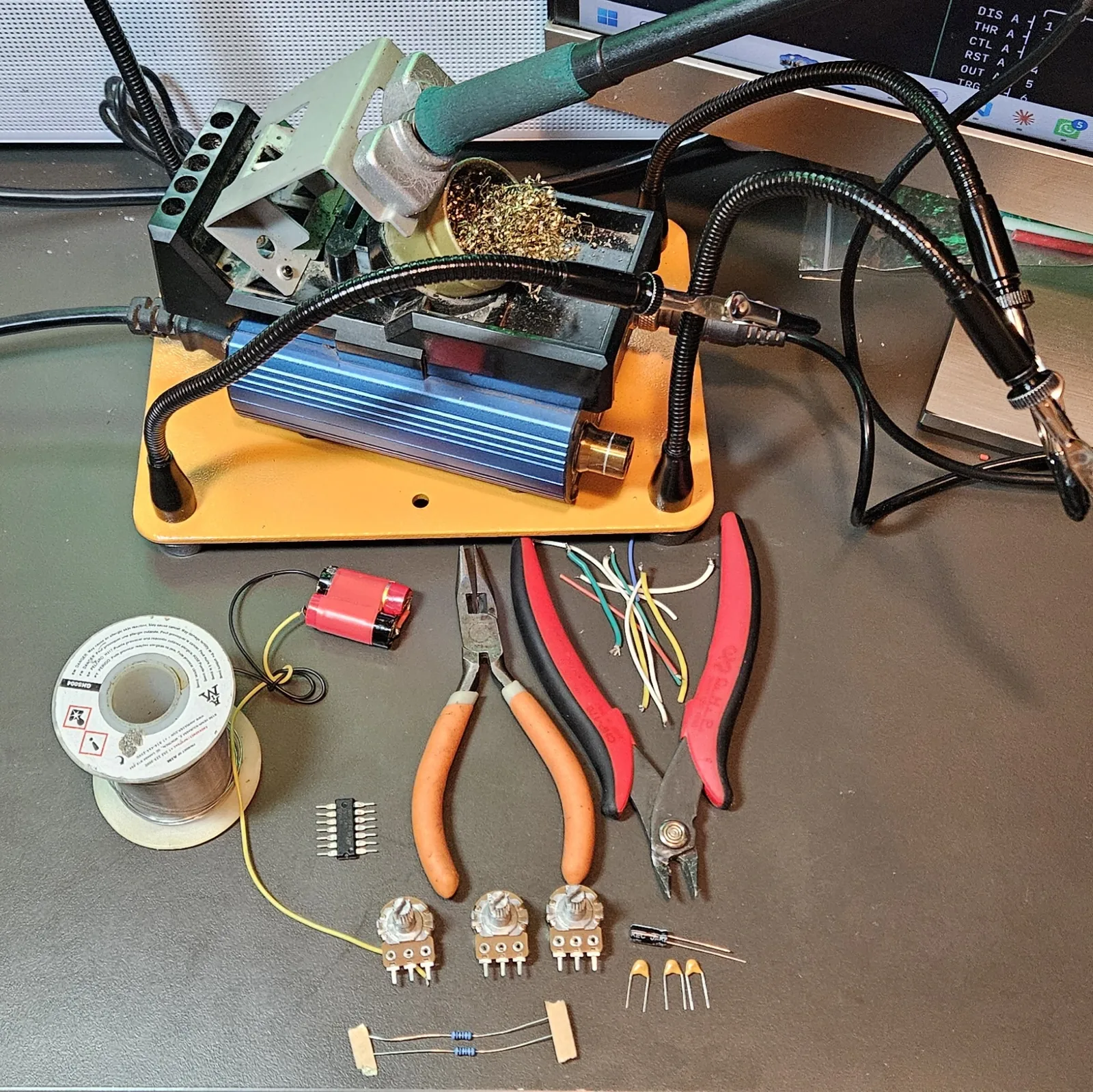
Step 1 Lay it all out first
Before the iron's even hot, get everything in front of you and eyeball it against the parts list. Dead-bug builds move fast once you start, and you do not want to be hunting for a cap with a molten joint waiting. Chip, three pots, the caps, the two 1K resistors, a rainbow of hookup wire, the vape pack, and your pliers — all present and accounted for.
Step 2 Splay the legs flat & find pin 1
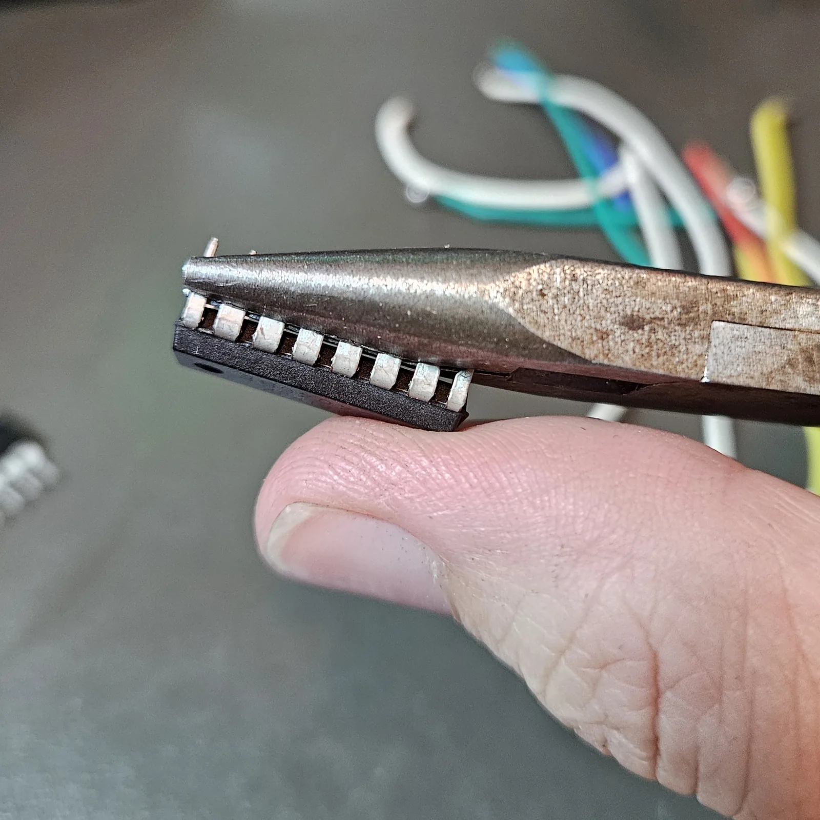
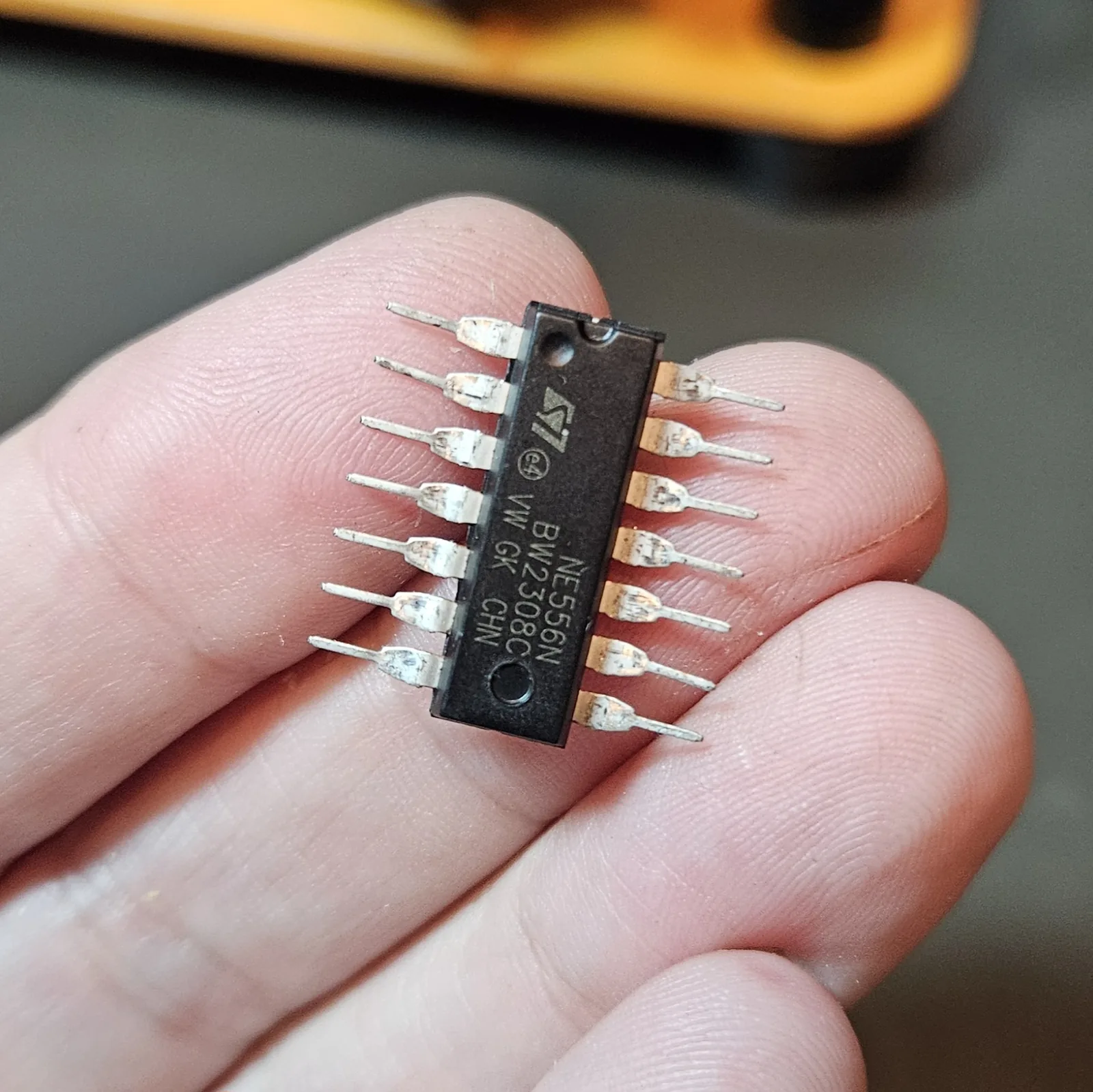
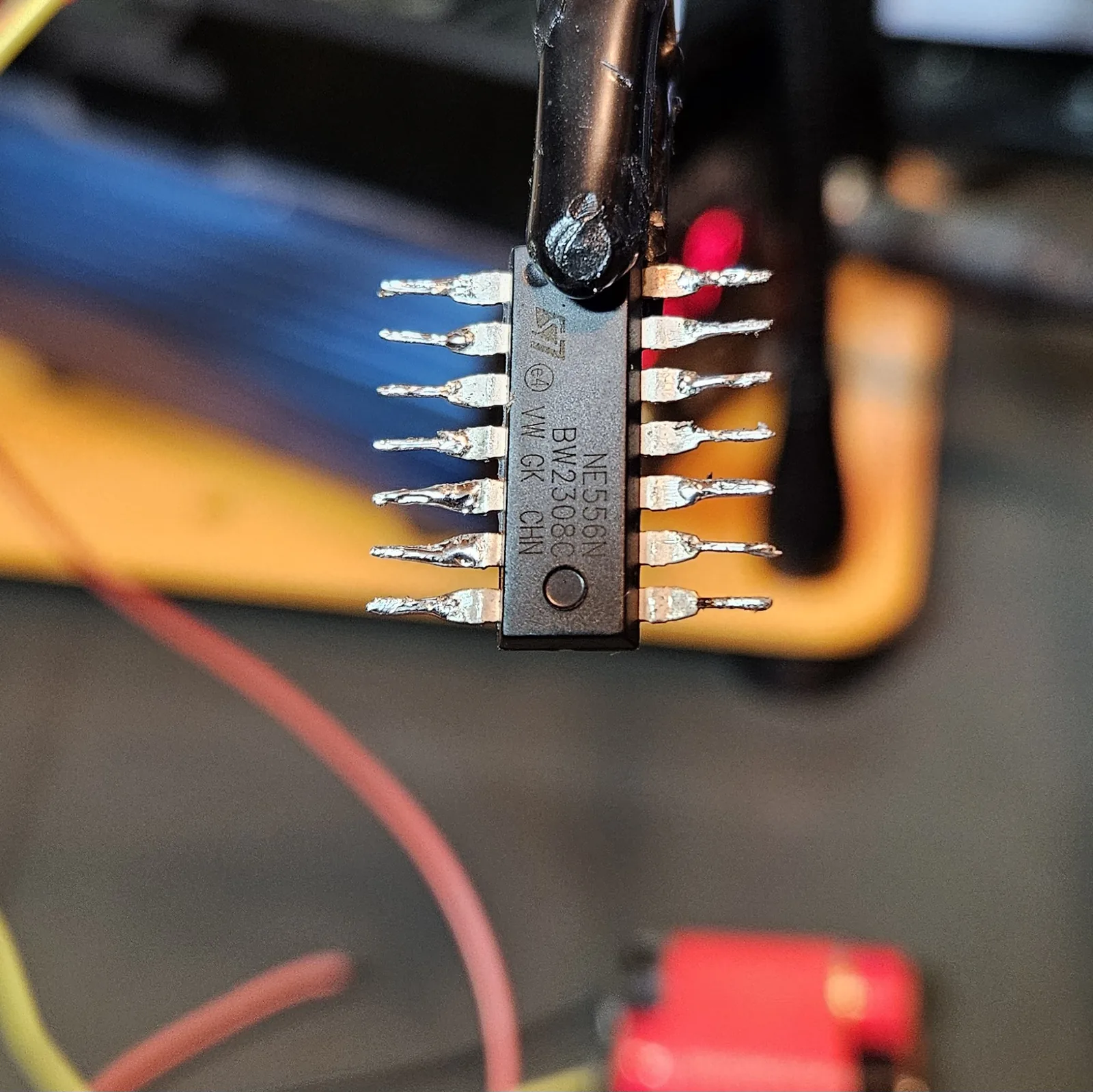
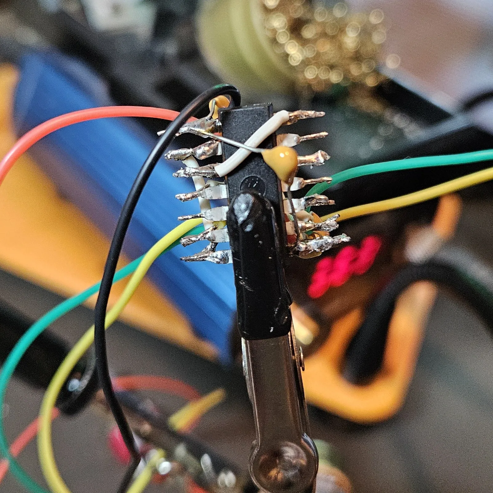
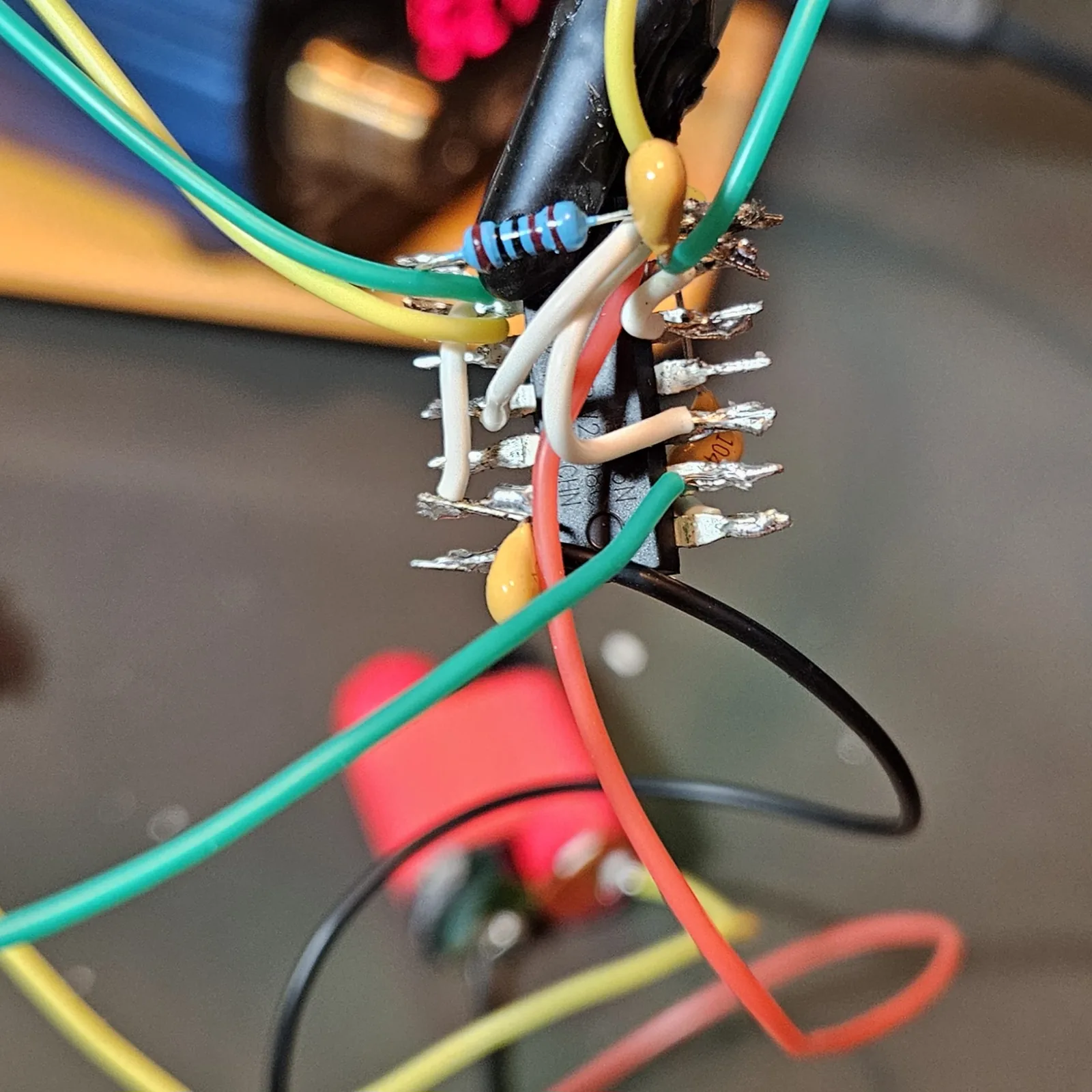
Here's my dead-bug trick: instead of gluing the chip to a board, I bend both rows of legs outward and flat with pliers, like a squished spider. Now it lies flat in the clamp, every pin sticks out on its own, and nothing's crammed together at DIP spacing. Way easier to solder to and to see. While you've got it in hand, find pin 1 — the notch at one end, and the little dimple next to pin 1. Everything downstream depends on getting that right.
Step 3 Clamp it and tin every pin
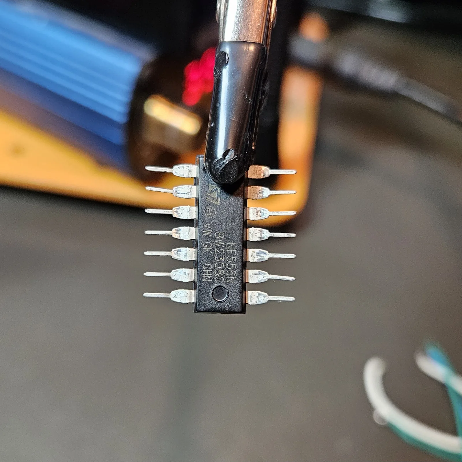
Lock the chip into the helping hands, belly toward you, and pre-tin all fourteen pins before you connect a single thing. A dab of solder on each leg now means every later joint is just “touch and go” instead of trying to melt solder, hold a wire, and balance the iron all at once. Tin your tips. Always tin your tips.
Step 4 Prep the on/off switch
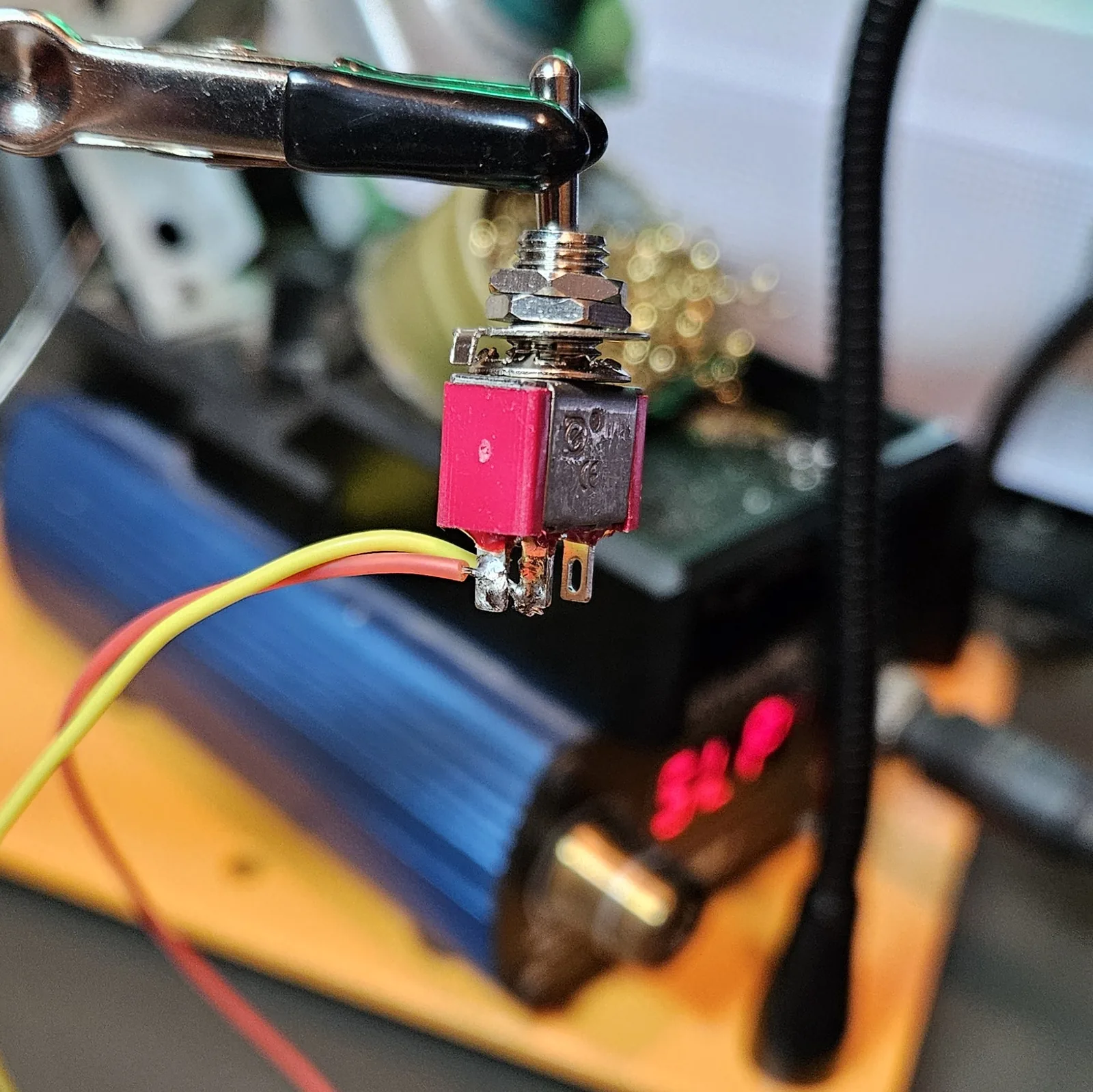
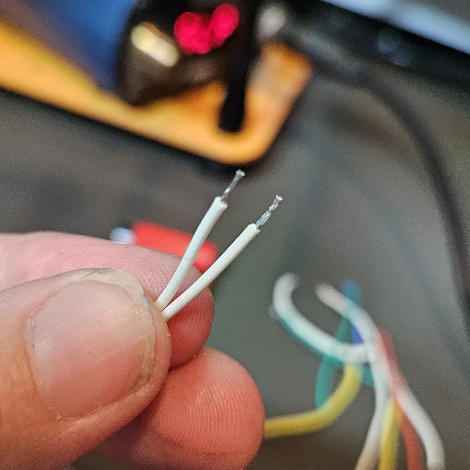
I like to wire the SPST toggle off to the side first, while it's easy to hold, then bring it into the circuit as a unit. It lives in the V+ line — battery positive in on one lug, out to the chip's V+ on the other. Do this now and you're not fumbling a bare switch later with everything else already soldered.
Step 5 Power: decouple, resets, rails
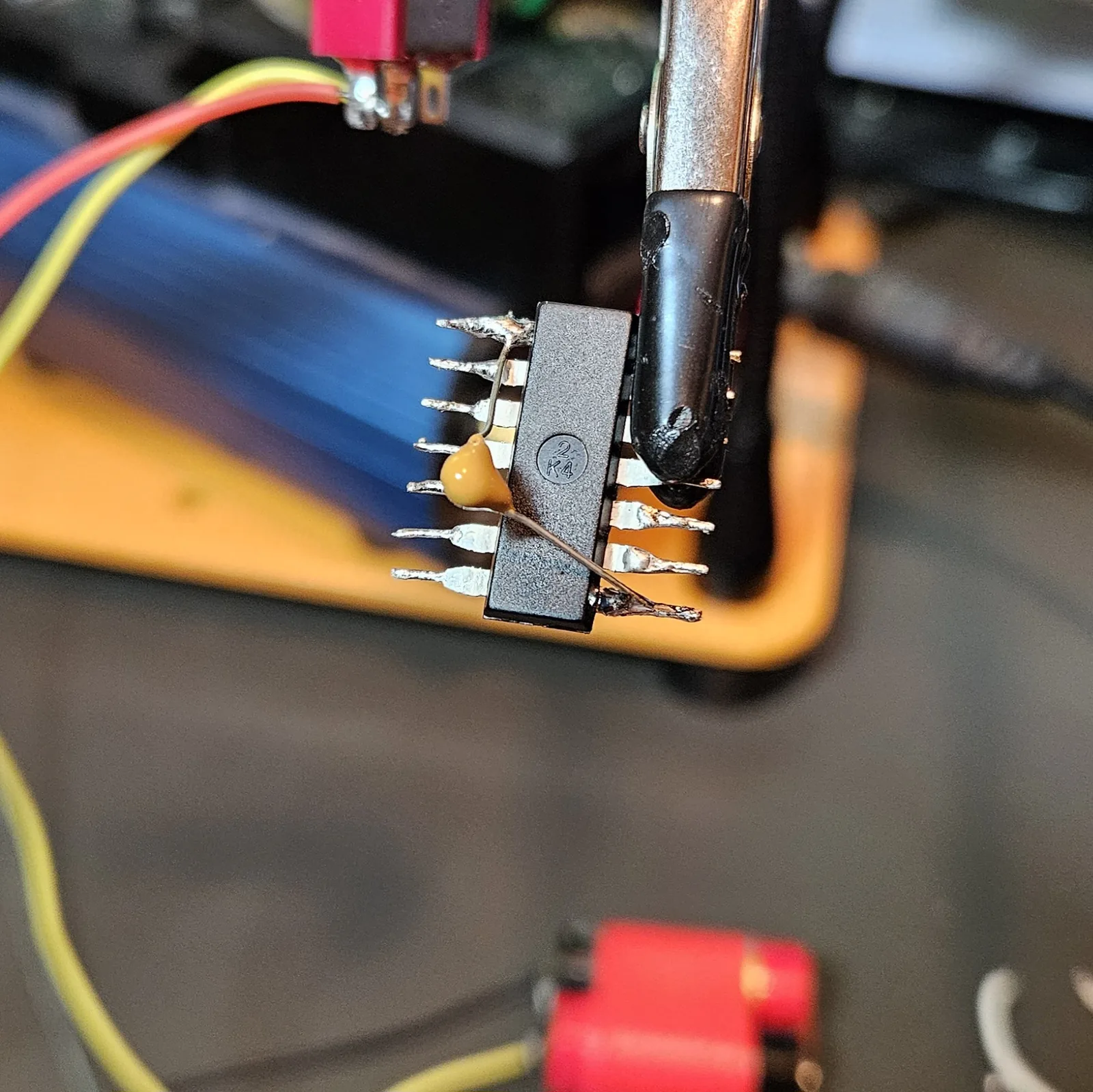
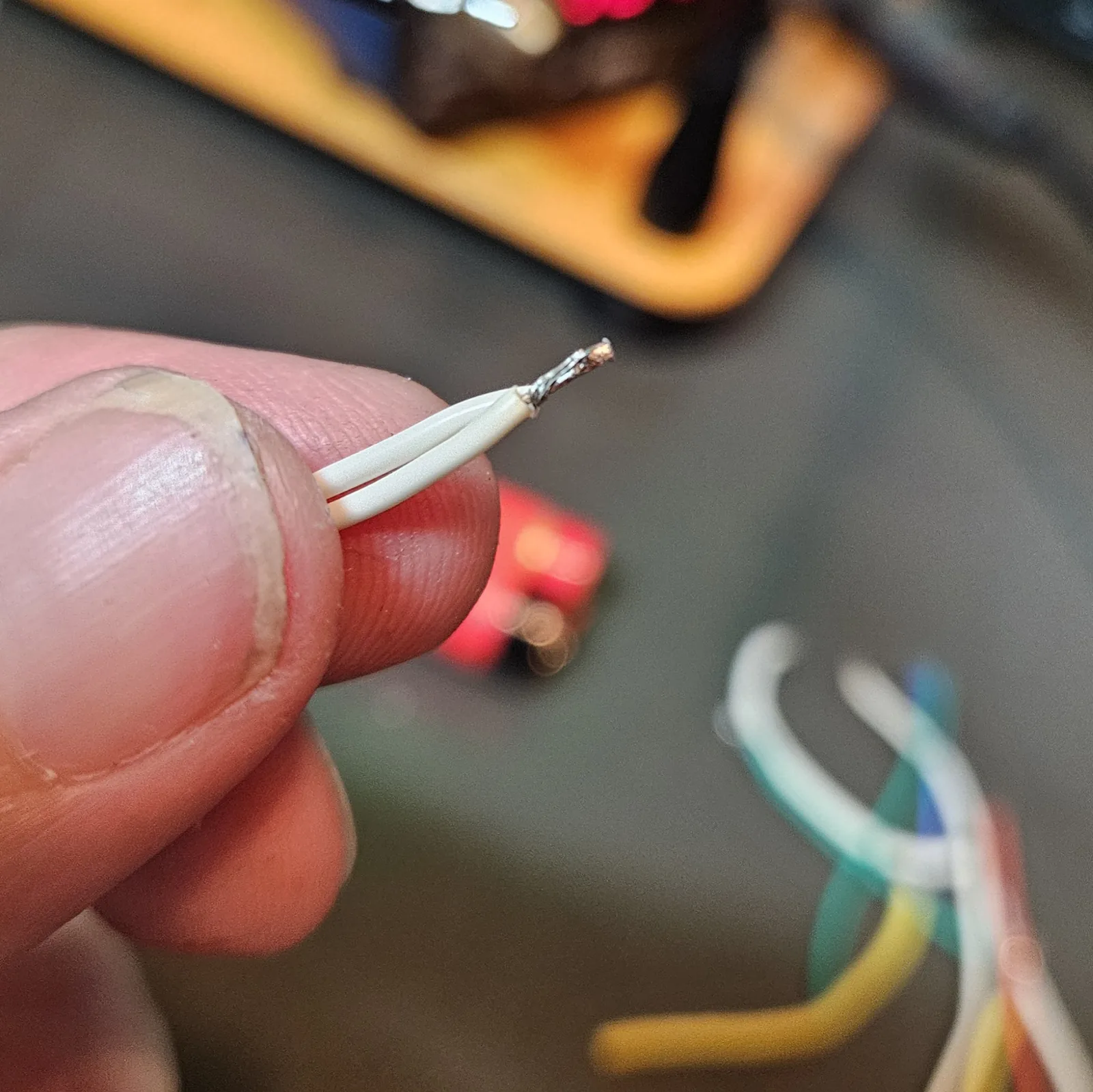
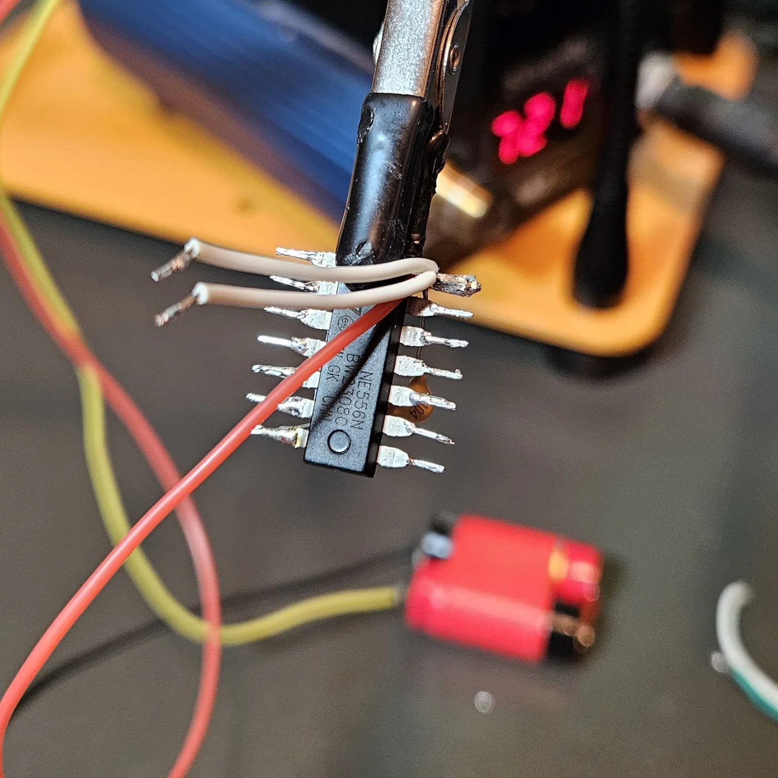
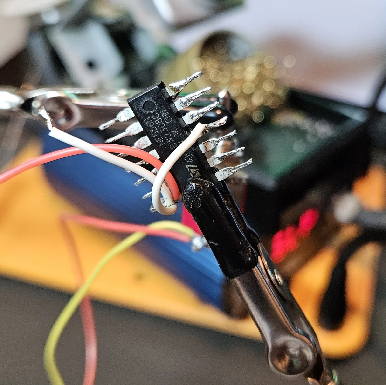
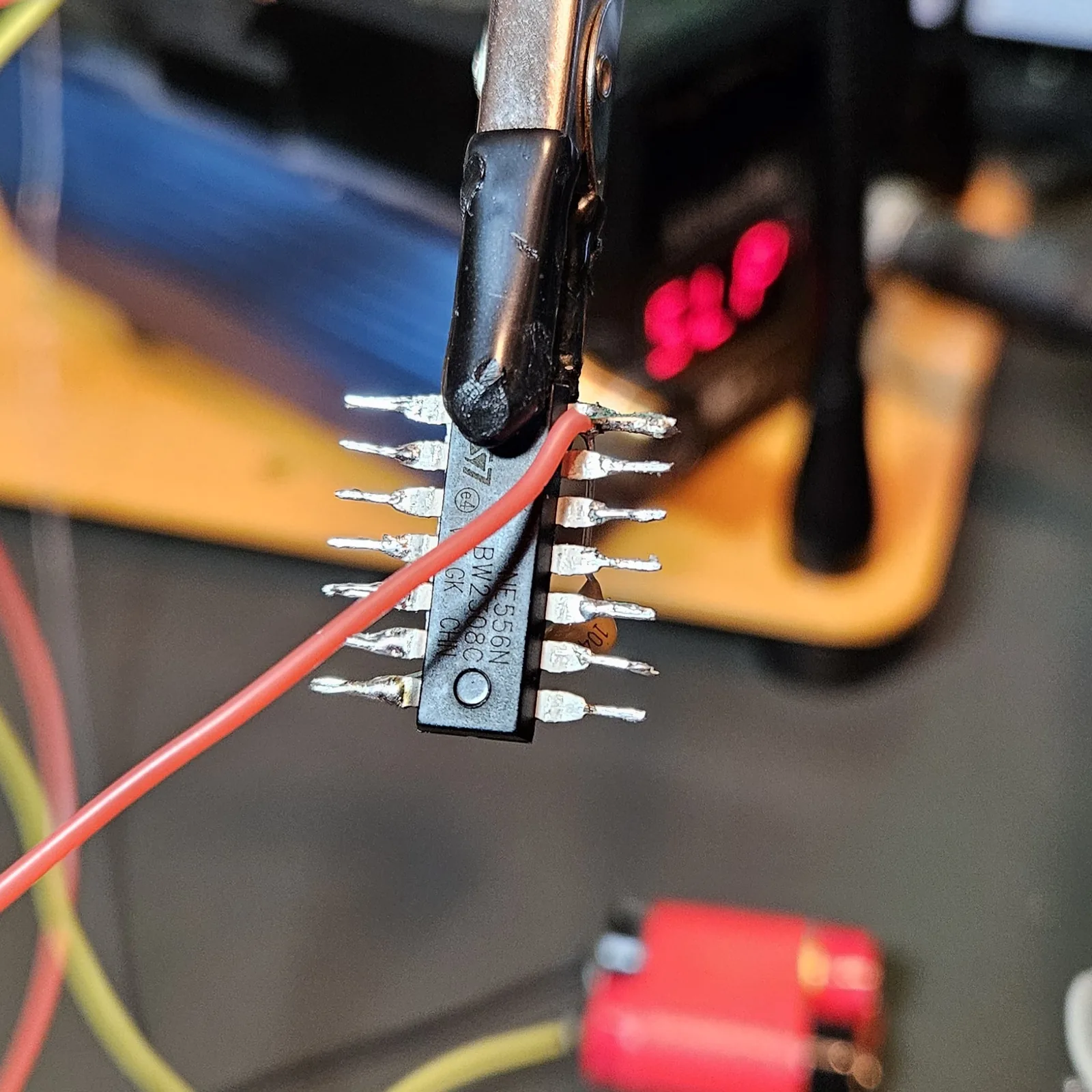
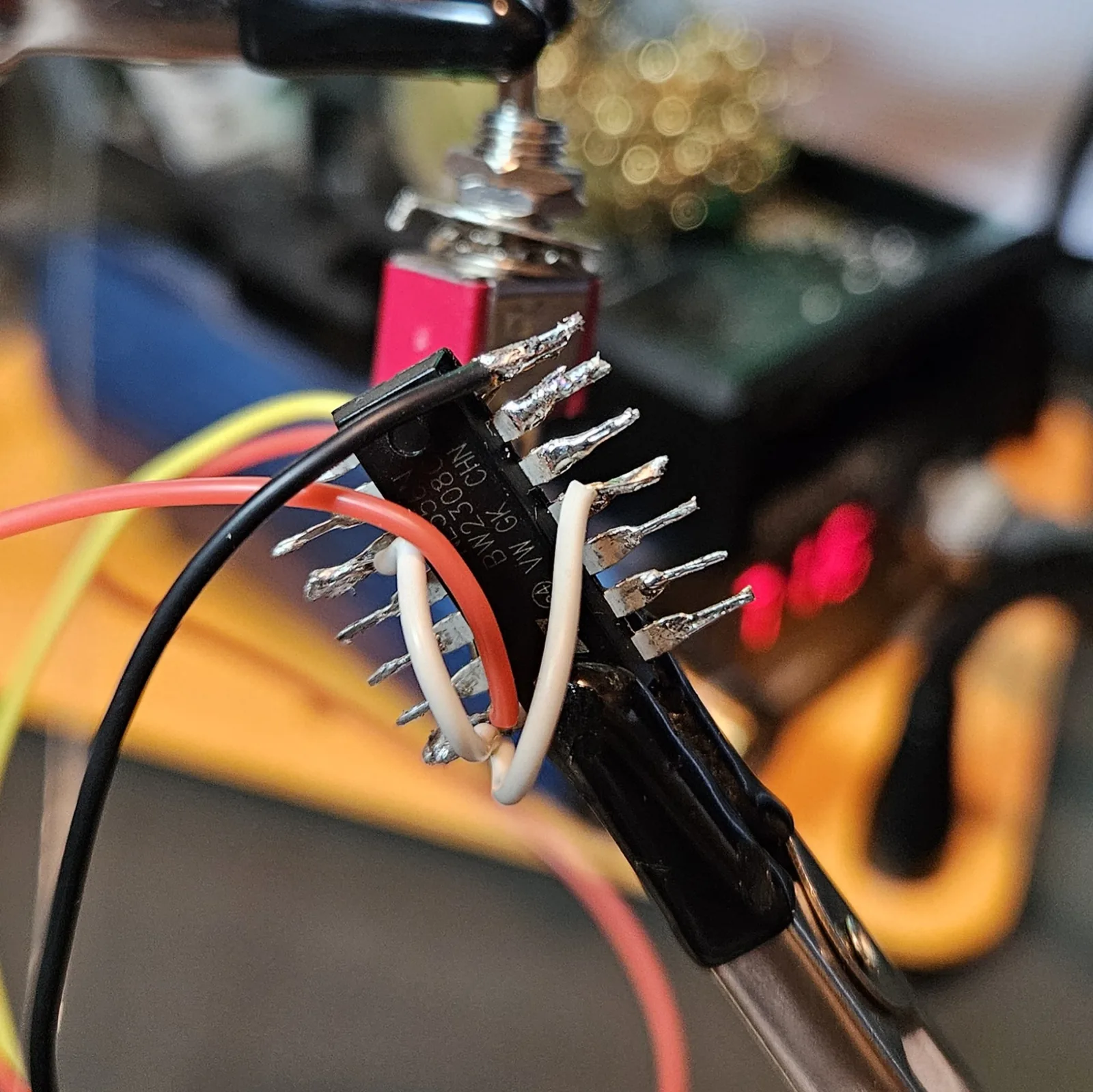
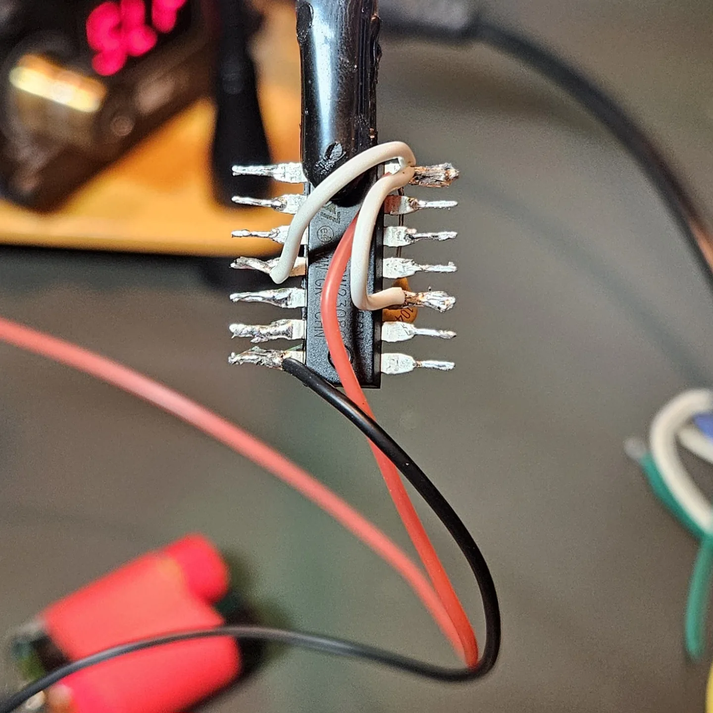
Power first, so the chip has a heartbeat before you hang the timing parts on it. Three jobs here: the 0.1 µF decoupling cap straight across V+ and ground at the chip (skip it and you get motorboating — that putt-putt-putt), the two reset pins tied high to V+ (a 556 with a floating reset just sits there silent), and the V+ and ground rails brought out to the switch and battery.
| Connect | To | Why |
|---|---|---|
| Pin 14 | V+ | Supply positive |
| Pin 7 | Ground | Supply negative |
| Pin 4 | V+ | Reset A held high (or it won't oscillate) |
| Pin 10 | V+ | Reset B held high |
| 0.1 µF | Pin 14 → Pin 7 | Decoupling, right at the chip |
Step 6 Timer A — the oscillator (pitch)
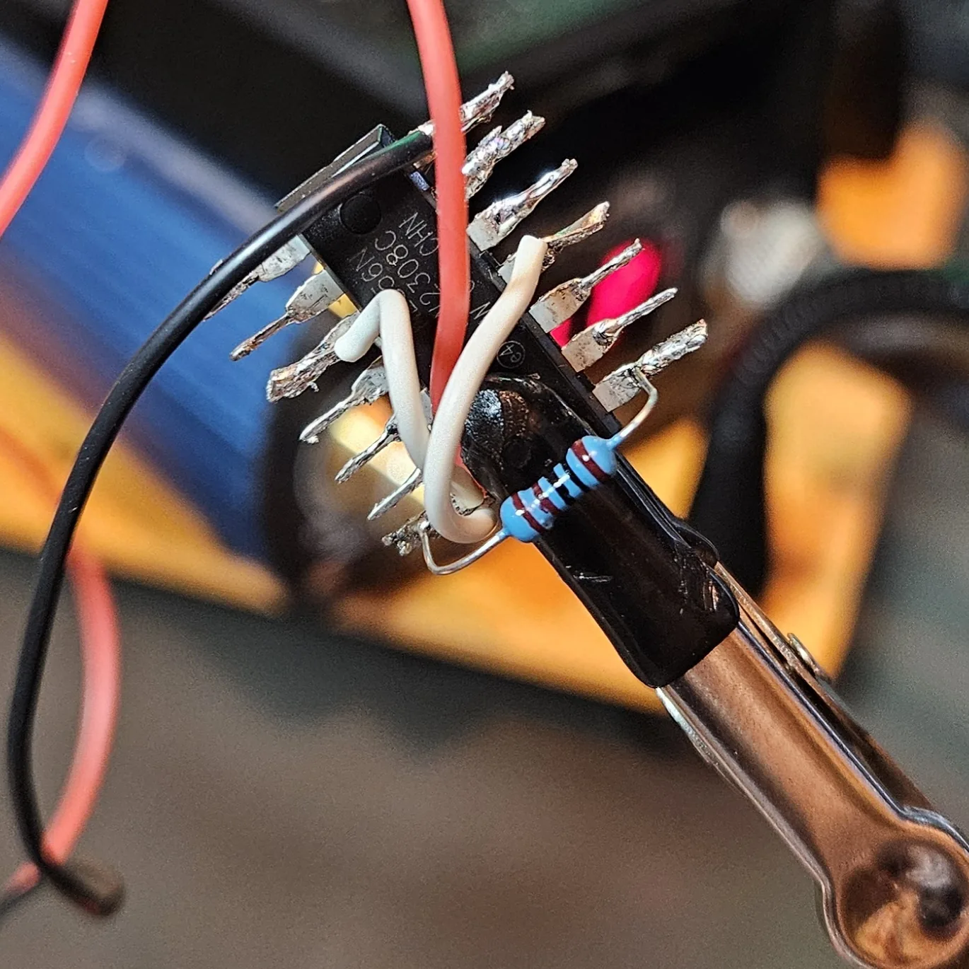
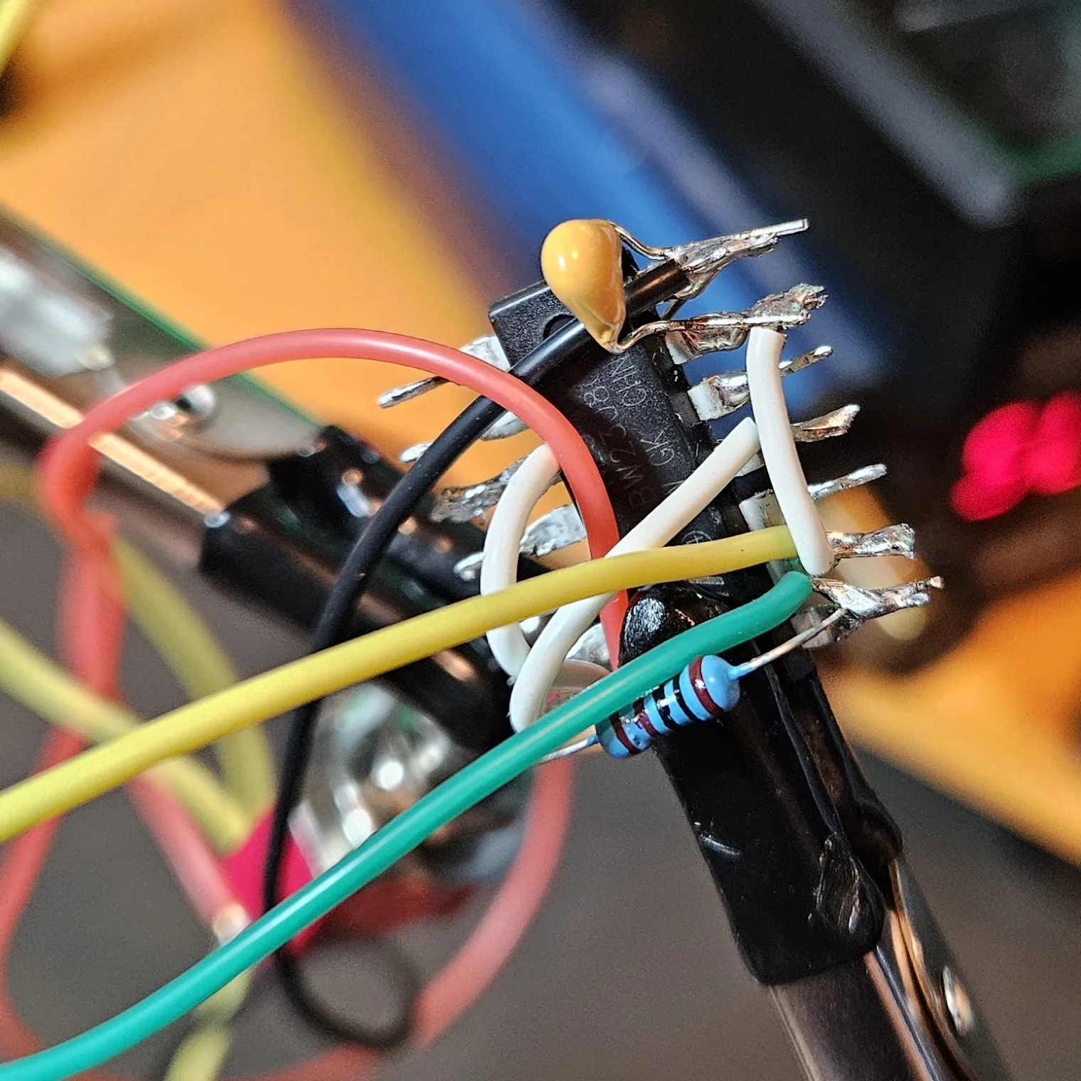
This half free-runs as a square-wave oscillator, and its knob is your pitch. Three moves: the 1K series resistor, the 1M pitch pot, and the 0.01 µF timing cap tying threshold and trigger down to ground. The 1K keeps the pot from ever hitting zero ohms and cooking itself.
| Connect | To | Part |
|---|---|---|
| Pin 1 | V+ | R1 = 1K |
| Pin 1 | Pin 2 | Pitch pot = 1M |
| Pin 2 | Pin 6 | Jumper (tie them together) |
| Pin 2 / 6 | Ground | C1 = 0.01 µF |
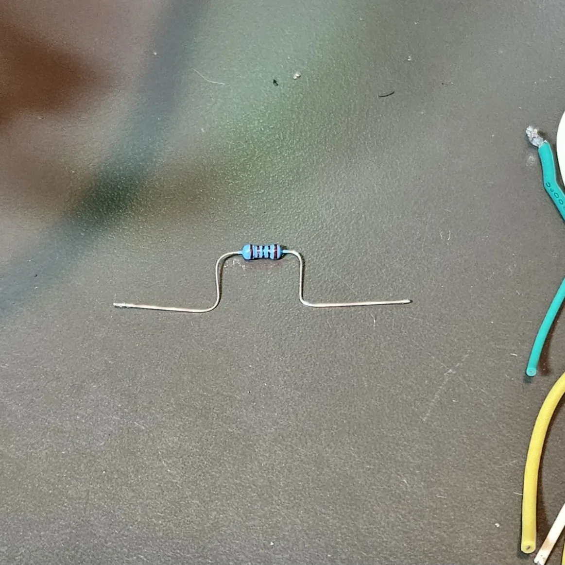
Form the resistor first. Bend its leads into a little flat-topped staple so it drops neatly across two points instead of flopping around.
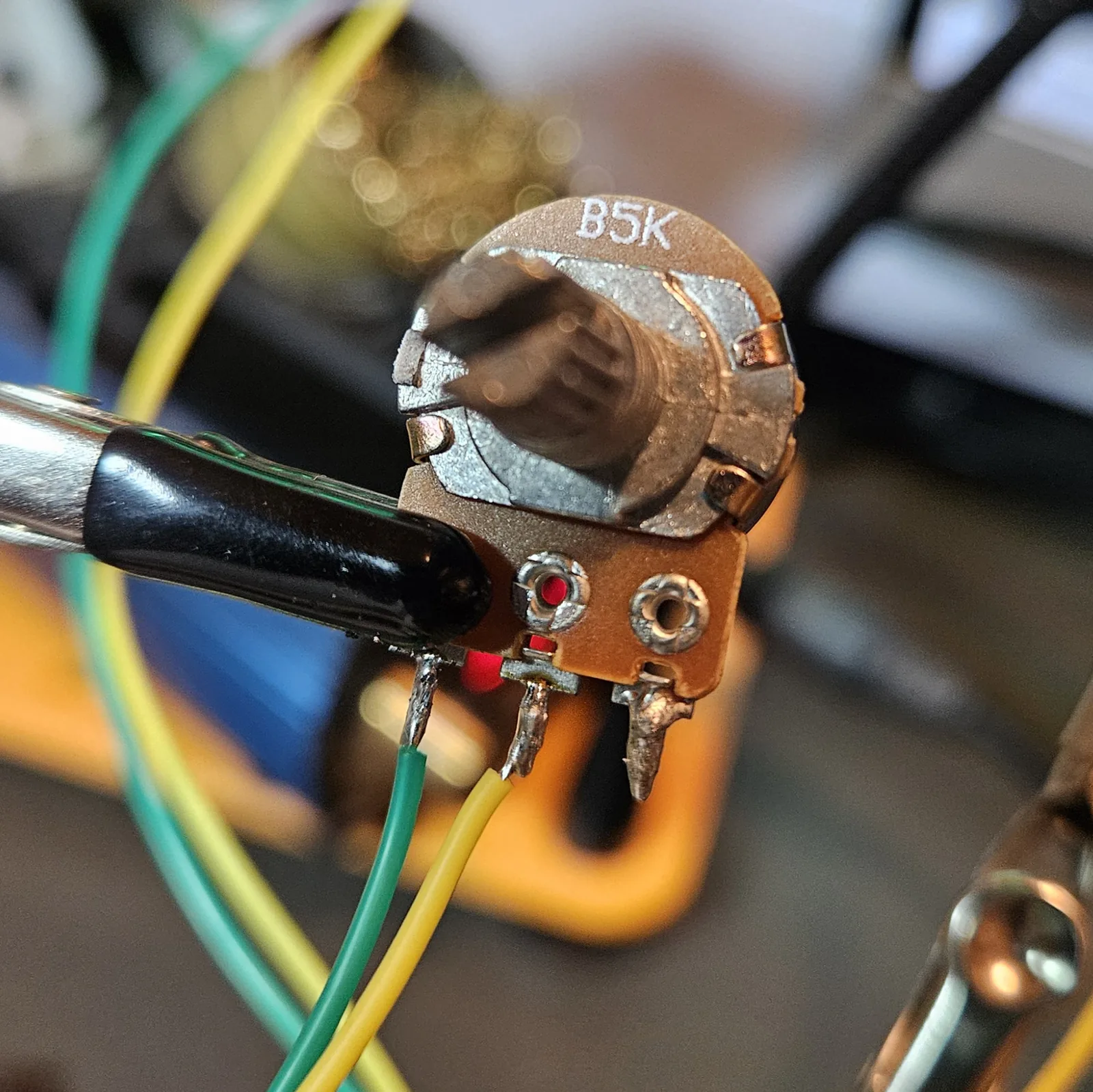
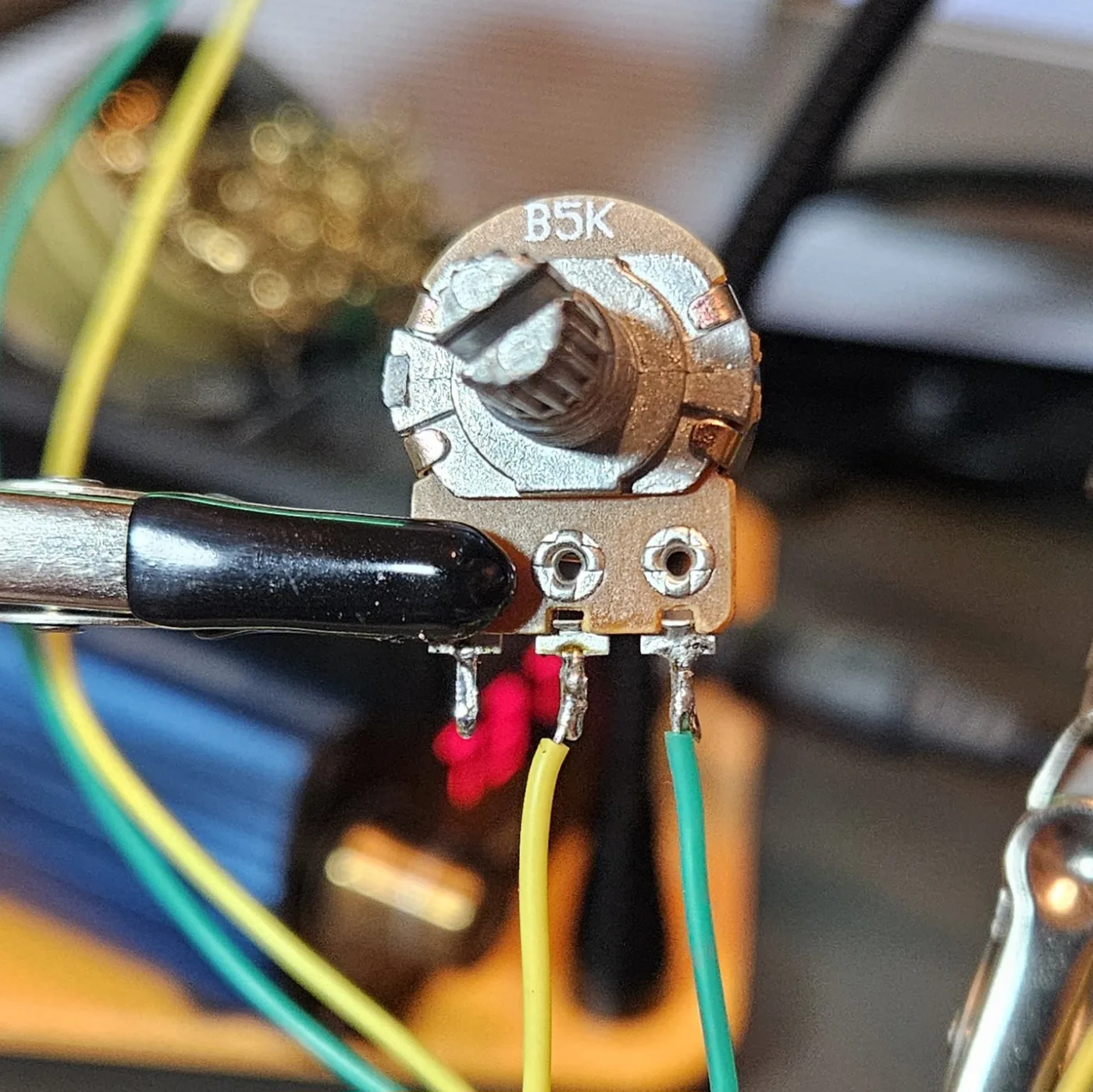
Now the pot — and snap that tab off. These pots have a little anti-rotation tab sticking off the side. Unless your enclosure has the matching hole drilled, it just holds the pot up off the panel. I grab it with pliers and snap it clean off so the pot seats flat. (Bend it flat if you 'd rather not fully remove it.)
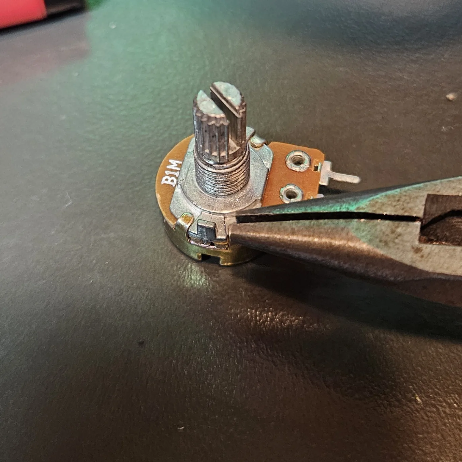
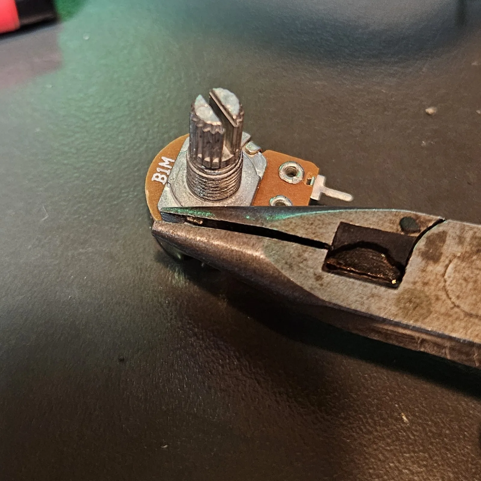
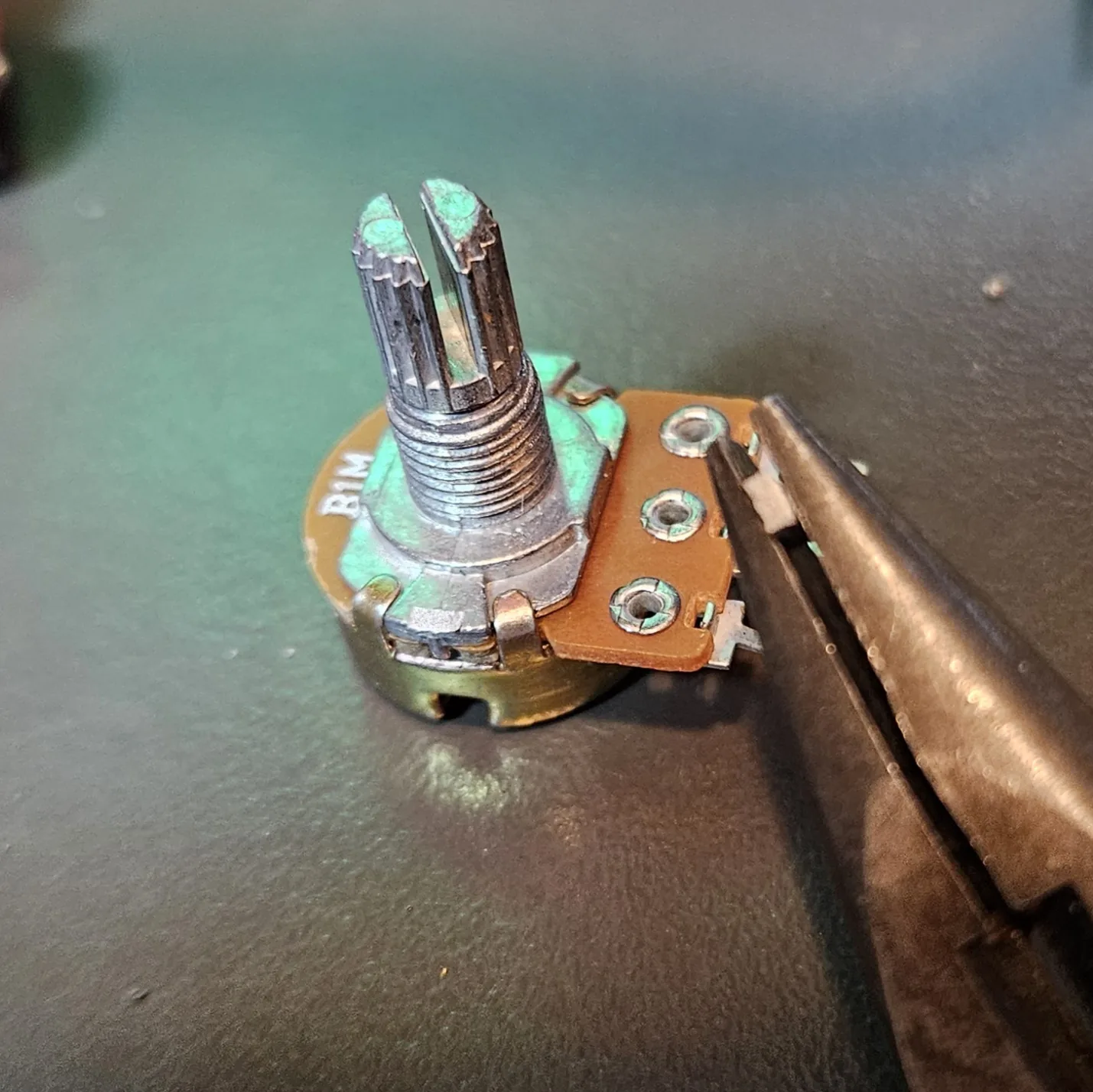
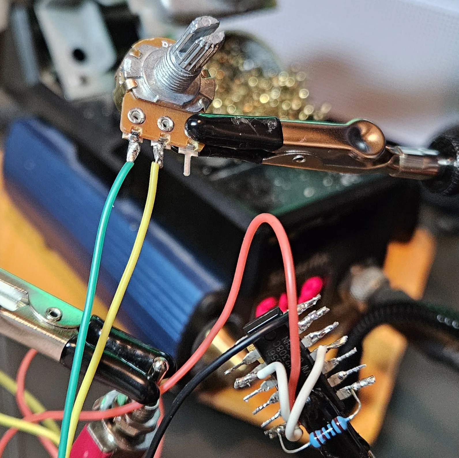
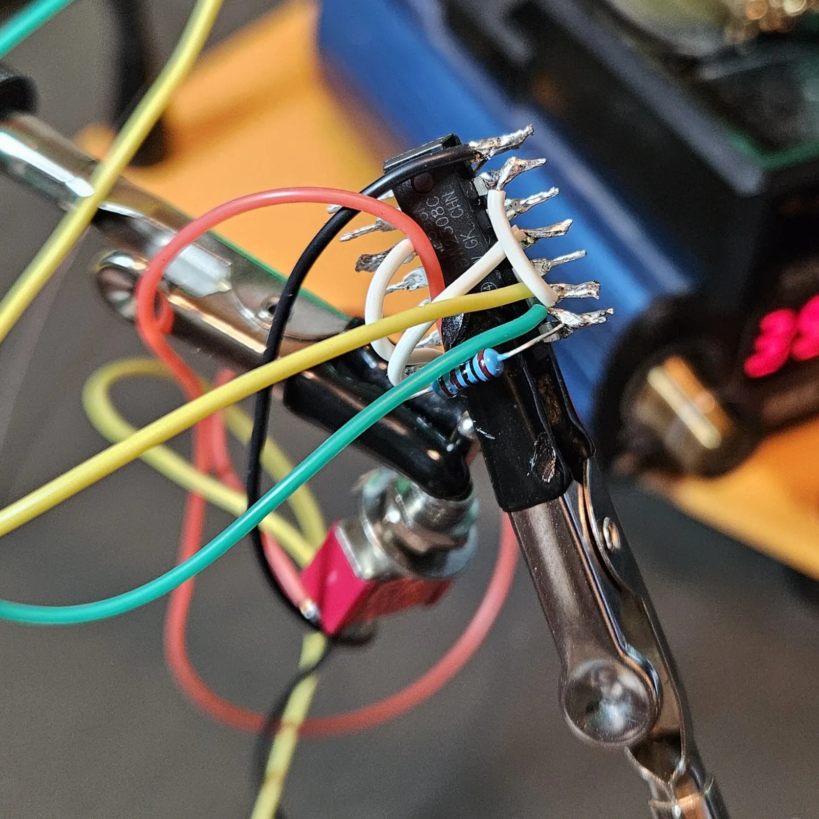
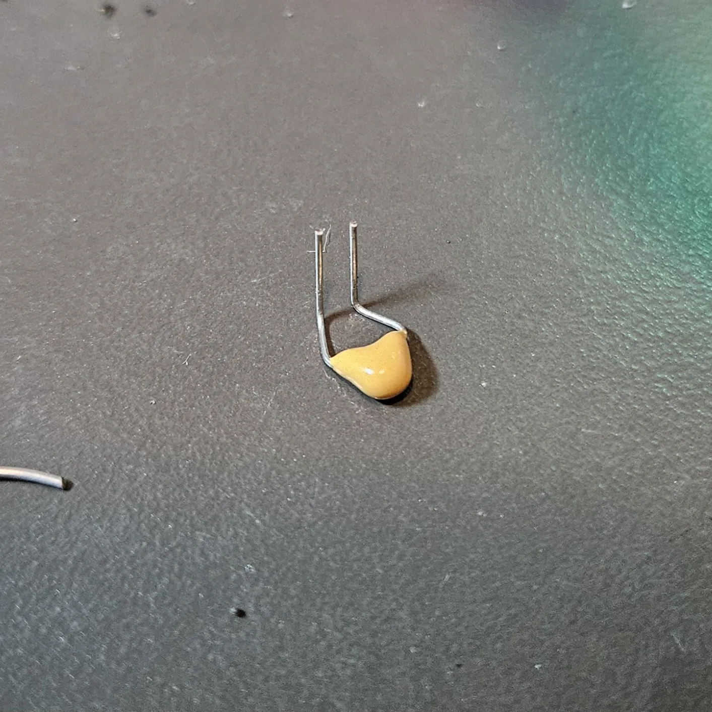
Then the timing cap. Same trick — pre-bend the legs into a U so it straddles the threshold/trigger junction and reaches ground.
Step 7 Timer B — the one-shot (shape) + the link
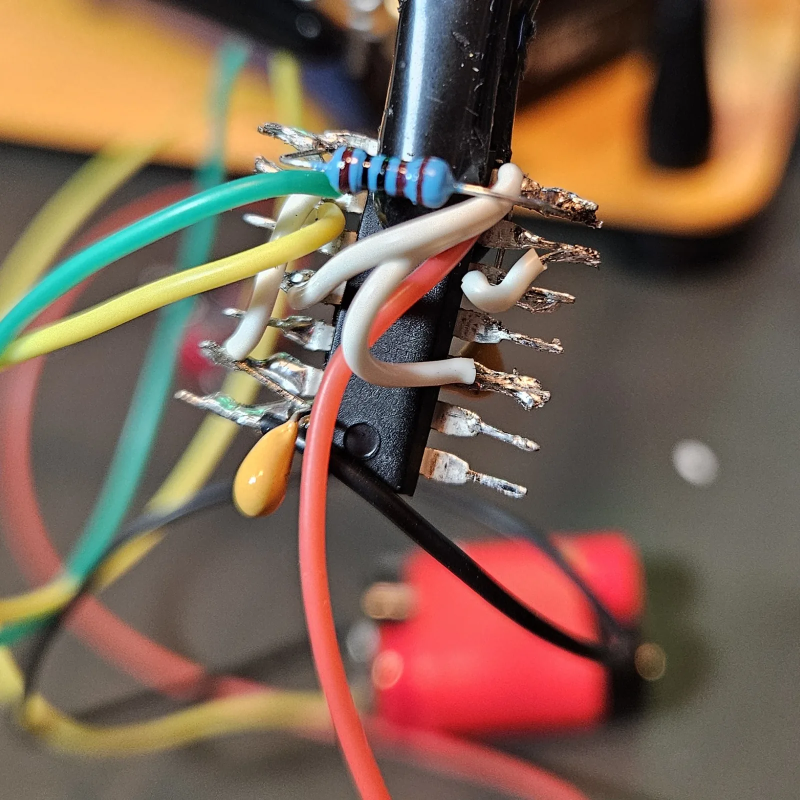
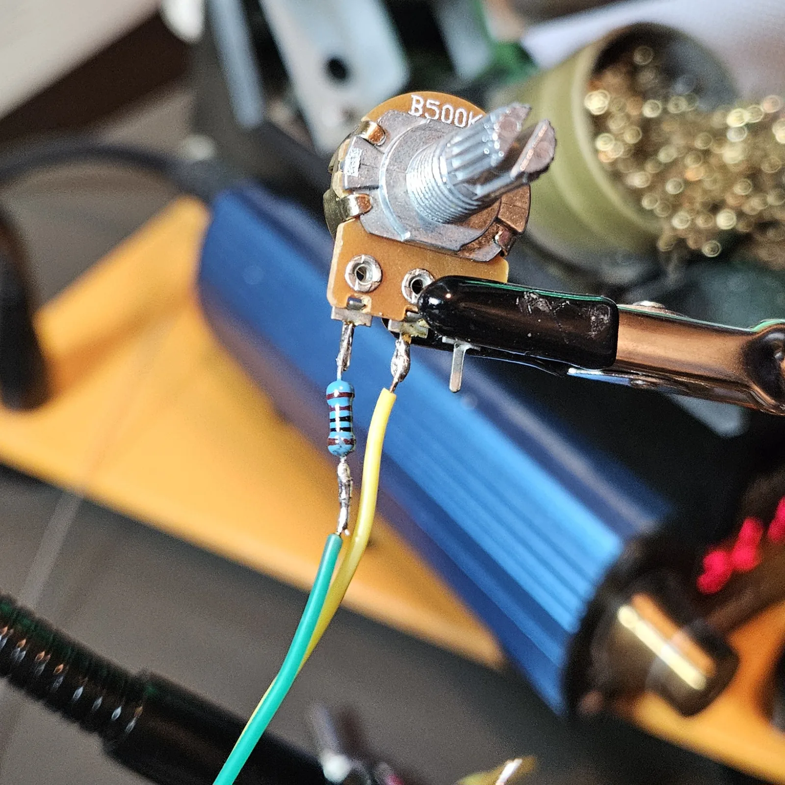
The second half is a monostable: it waits for a kick, then fires one pulse. Its knob sets how wide that pulse is — your shape. Same recipe as timer A, but the pot (I used a B500K here for a punchier range) charges the cap through its own 1K . Solder that 1K right onto a pot lug so it travels with the pot.
| Connect | To | Part |
|---|---|---|
| Pin 13 | Pin 12 | Jumper (tie them together) |
| Pin 12 / 13 | V+ | R2 = 1K + Shape pot (500K here) |
| Pin 12 / 13 | Ground | C2 = 0.01 µF |
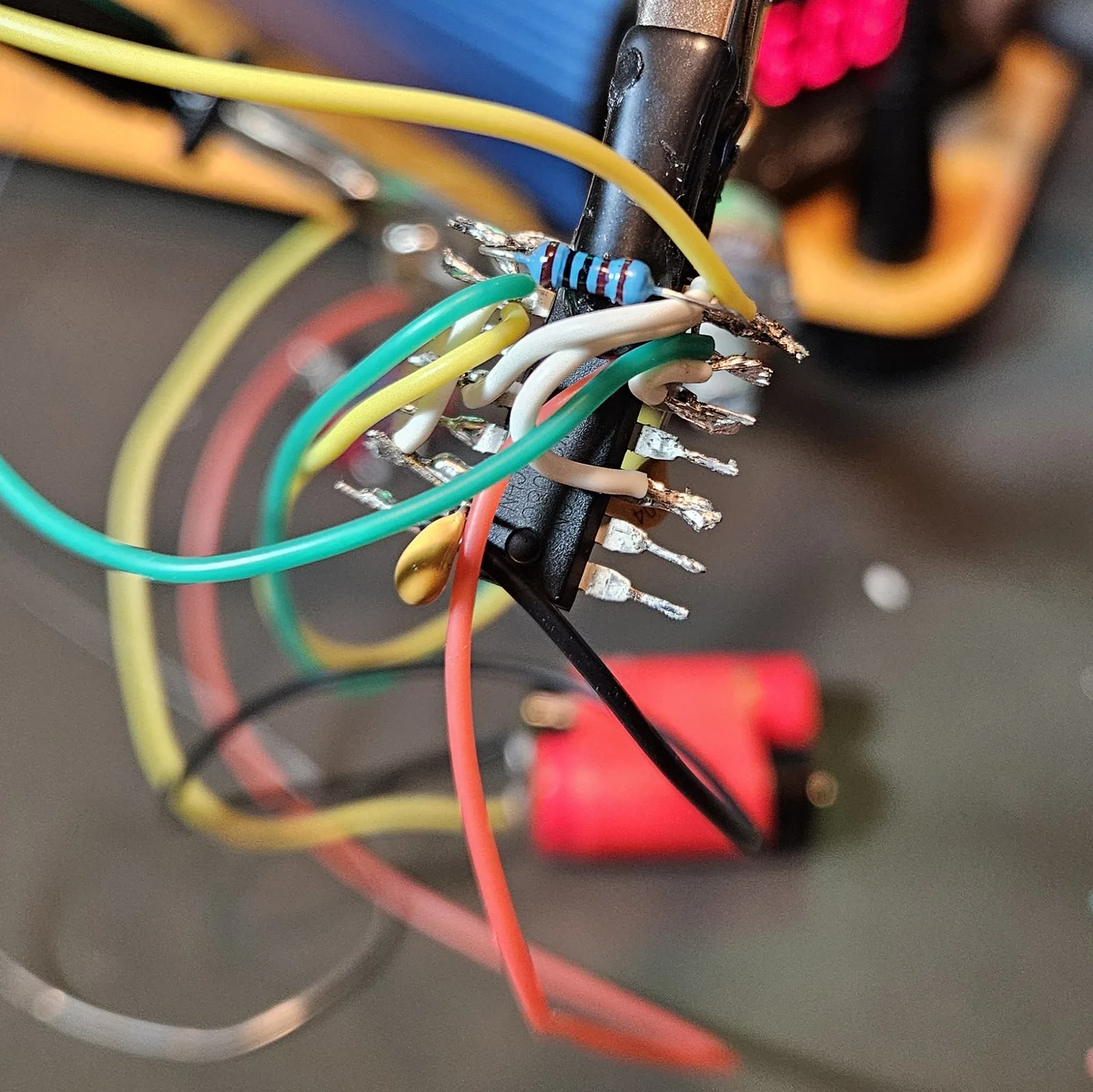
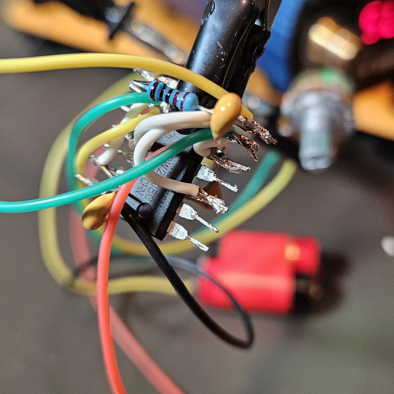
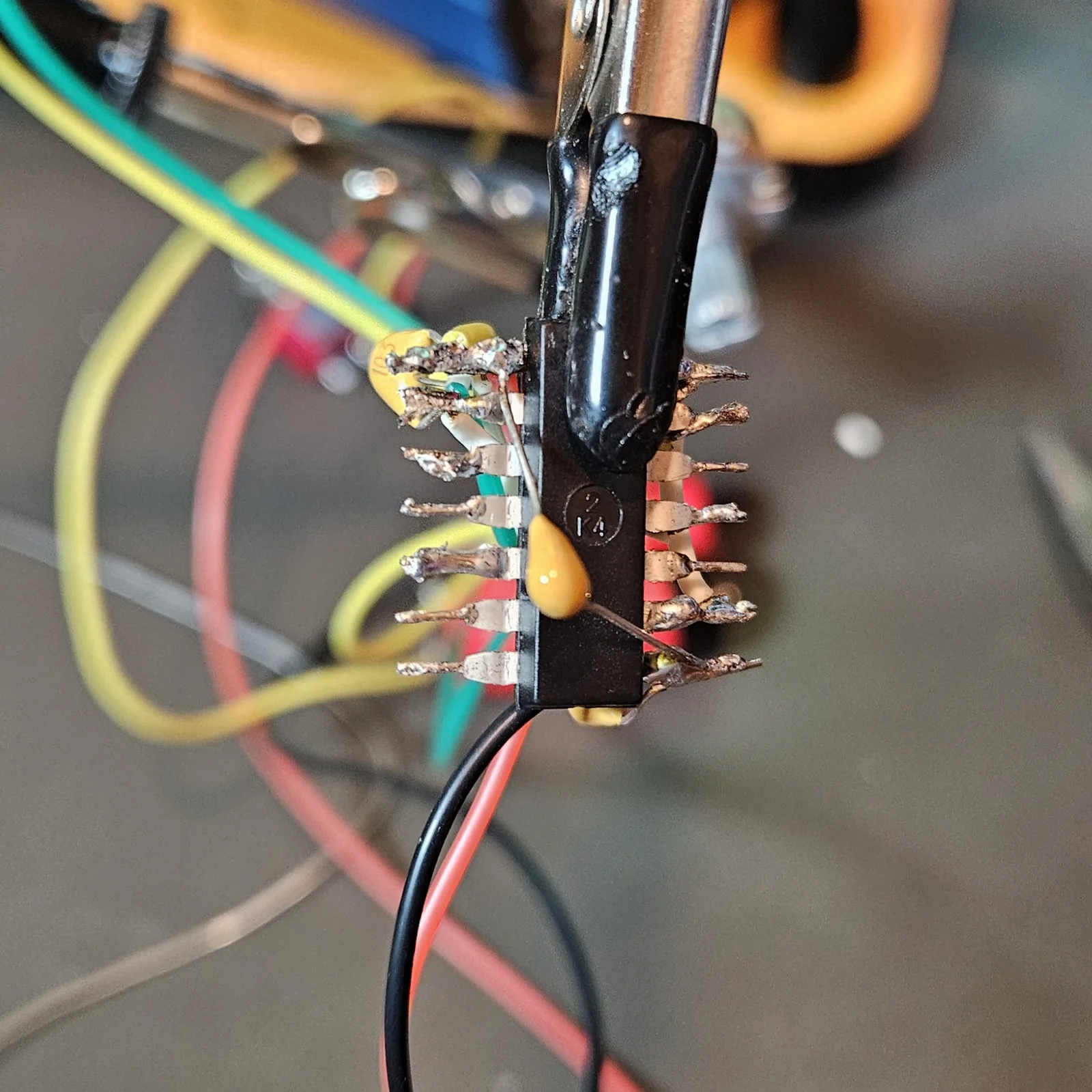
And the one wire that makes it an APC: tie timer A's output to timer B's trigger. Every cycle of the oscillator re-fires the one-shot — that's the whole stepped-tone trick, in a single jumper.
| Connect | To | Why |
|---|---|---|
| Pin 5 (OUT A) | Pin 8 (TRG B) | Oscillator triggers the one-shot |
Step 8 Volume & the way out
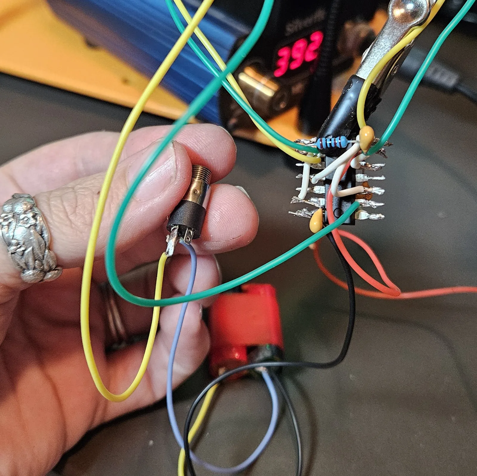
Timer B's output is a fat square wave swinging nearly rail-to-rail. Block the DC with the 10 µF electrolytic (mind the stripe — minus leg toward the output), run it through a volume pot, then out. On this build I ran it to both an onboard speaker and a switching output jack, so plugging a cable in cuts the speaker and sends it to an amp. (I grabbed a 5K for volume this time; 10K is the usual — anything in that range is fine.)
| Connect | To | Part |
|---|---|---|
| Pin 9 | Volume pot (top) | C3 = 10 µF (+ toward pin 9) |
| Volume wiper | Jack tip (switching) | — |
| Jack “normal” lug | Speaker (+) | Plug cuts the speaker |
| Speaker (−) / Jack sleeve | Ground | — |
Step 9 Fire it up
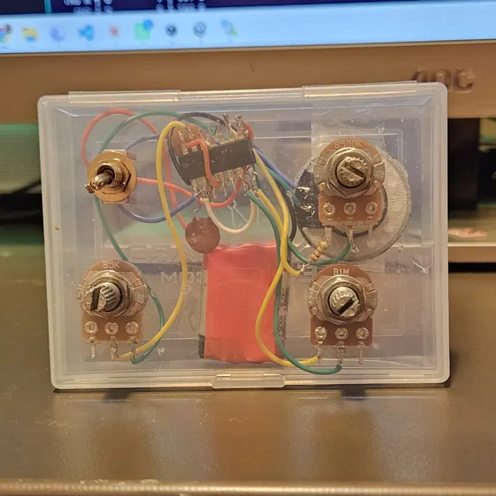
Flip the toggle and it should drone the second it powers on. Sweep pitch and the note moves; sweep shape and the timbre steps and stutters, dropping out entirely at the extremes — that's normal, the one-shot running out of room. Here's the finished spider of a thing, and the guts of the first one boxed up.
Voltage note tap to expand / collapse
The NE556 runs from about 4.5V up to ~15V, and more volts means a louder, hotter output. Power it from at least two vape cells in series (7.4V — three gives you 11.1V) or a 9V battery.
Step 10 If it won't sing
Point-to-point means every fault is a joint or a pin you can actually see. In order of likelihood:
- Dead silent? Check pins 4 and 10 are actually sitting at V+. Reset pins left floating or low is the classic APC no-sound bug.
- Still nothing? Confirm the 5→8 link, and that V+ (pin 14) and ground (pin 7) are solid.
- Faint, or only a tick? Check the 10 µF output cap polarity (+ toward pin 9) and that your timing caps landed on ground.
- Buzzy / motorboating? You skipped the 0.1 µF decoupling cap, or a joint is cold. Reflow anything that looks dull or blobby.
- Runs but the pot does nothing at one end? That's the 1K series resistor earning its keep - expected. If a pot does nothing at all, you're probably on the wrong two of its three lugs (use the wiper + one end).
Going further: CV in & another way out
This is where the APC stops being a toy and starts playing with your other gear. The 555/556 hands you a modulation input for free, and tapping a second output is a two-wire job. Everything here is optional - add what you want, skip what you don't.
CV inputs (pitch & shape)
Each timer has a Control Voltage pin that sets its internal threshold. Push a voltage in and you bend the timing directly - no extra circuitry, just a jack and a resistor. Pin 3 modulates pitch; pin 11 modulates shape.
| Connect | To | Part |
|---|---|---|
| Jack tip | Pin 3 (pitch CV) or Pin 11 (shape CV) | ~100K series resistor |
| Jack sleeve | Ground | - (shared ground is mandatory) |
Want a depth knob? Put a pot in front of the jack as an attenuator (voltage in on one end, ground on the other, wiper into the 100K). Three things worth knowing before you patch it to anything:
- It's not 1V/oct. The response is nonlinear - gorgeous for LFOs, envelopes, and expression pedals, useless for tracking a keyboard in tune. Lean into it as a modulation input, not a precision one.
- Keep CV inside 0–V+. The series resistor limits current; if you're feeding it from bigger modular voltages, a clamp diode to the supply rail adds cheap insurance.
- Share ground. Tie the jack sleeve to the APC's ground and to the source's ground, or you get silence and hum. Running on a battery keeps the box floating, which is actually a gift here - it dodges ground loops - but the sleeve-to-ground wire is not optional.
Another signal out
Two useful taps, depending on what you want to drive:
| Output | Tap from | How |
|---|---|---|
| Line / audio out | Pin 9 (OUT B) | 10 µF cap → volume pot → wiper → 1K series → jack tip; sleeve to ground. Use a switching jack so plugging in cuts the internal speaker. |
| Clock / sync out | Pin 5 (OUT A) | 1K series → jack tip; sleeve to ground. This is the raw oscillator square at the pitch rate - great for clocking other boxes. |
Why the attenuation on the audio out: that square wave is hot - nearly the full supply, peak-to-peak. Straight into a line or pedal input it's harsh and way too loud, so the pot knocks it down to something friendly. Your CV range runs from 0V up to whatever you're powering the chip from, so the supply sets how much room you have to sweep in.
One and a half: bolting on a second one-shot
This is the mod that turns the Screamer into a different instrument. Right now your oscillator fires one one-shot. Hang a plain NE555 off the same trigger as a second one-shot, and the two voices come out harmonically related — because both are counting from the same clock, their pulse widths land in whole-number relationships instead of drifting against each other. You get something that reads as harmony out of a circuit with no pitch tracking in it anywhere.
Your 556 already is two of the three timers, so this costs you one 8-pin chip. Half an APC bolted onto the one you built — hence “one and a half.”
Credit where it's due: the shared-trigger trick comes from ozerik's “Atari Punk Console One and a Half” on Instructables, which builds all three timers from scratch as separate 555s. The idea is his. The wiring below is my own, adapted to a 556 you've already got working — go read his build too, it's a good one.
The NE555, from above
Same notch-marks-pin-1 rule. Half the pins of the 556, same logic.
What to add
- 1× NE555 timer, 8-pin DIP — spot it: NE555 printed on top, notch marks pin 1
- 1× 1M pot — your second Shape knob (marked B1M)
- 1× 1K resistor — series protection for that pot
- 1× timing cap — 47nF (473) or 100nF (104). Deliberately not the same as timer B's — see the harmony note below
- 3× 1K resistors — the mixer
- 2× 220Ω resistors — optional supply isolation, one per chip
Wiring the second one-shot
| Connect | To | Part / note |
|---|---|---|
| Pin 1 | Ground | — |
| Pin 8 | V+ | Supply positive |
| Pin 4 | V+ | Reset high — floating reset = silence |
| Pin 6 | Pin 7 | Jumper (tie them together) |
| Pin 6/7 | V+ | 1K + Shape 2 pot (1M) in series |
| Pin 6/7 | Ground | Timing cap — 47nF or 100nF |
| Pin 2 | 556 pin 5 | ⭐ The shared trigger. Same node that already drives 556 pin 8 — this one wire is the whole mod |
| Pin 3 | Mixer | Output of voice 2 |
| Pin 5 | — | Leave open, or 10nF to ground if it gets noisy |
Trigger inputs are high-impedance, so the 556's output drives both one-shots without complaint. You're tapping pin 5, not rerouting it — the original link to pin 8 stays exactly as it was.
Mixing the two voices
You cannot tie two timer outputs straight together — one will pull high while the other pulls low and they'll fight, which sounds bad and is unkind to both chips. Blend them through resistors instead:
| Connect | To | Part |
|---|---|---|
| 556 pin 9 (voice 1) | Mix node | 1K |
| 555 pin 3 (voice 2) | Mix node | 1K |
| Mix node | Ground | 1K — halves the level, keeps it civil |
| Mix node | Your existing output chain | 10 µF → volume pot → speaker / jack |
Where the harmony actually lives
The two timing caps. Timer B uses 0.01 µF (10nF); give the 555 something clearly different — 47nF or 100nF. The ratio between those two caps sets the interval between the voices, so that choice is the musical decision in this whole mod. Fit both with the same value and you've built two timers doing the same job in unison, which is a lot of soldering for no new sound. Socket the cap if you want to audition a few.
Two things worth doing
- 220Ω on each chip's V+ pin. Cheap insurance, and one of the better tips in ozerik's build: it isolates the 555's famously noisy supply spikes and limits current through the pots. Atari Punk Consoles are notorious for cooking pots.
- Decouple the new chip too. Three timers now share one supply, and the 555 is a rude neighbour — it dumps current spikes onto the rail every time it switches. Put a 0.1 µF right across the 555's pin 1 and pin 8, as close to the legs as you can get it, exactly like the one on the 556.
…and then keep going
Nothing stops at two. Every extra one-shot is just another copy of the 555 section — its own cap, its own pot, its own 1K into the mix node, all triggered from the same pin 5. Four or five of them and the thing stops being a noise box and becomes a drone organ.
That's the lot. Build the core first, get it screaming, then start drilling holes for jacks - every mod here hangs off a single pin you can reach. Show me what you make.
The Atari Punk Console descends from Forrest M. Mims III's “Stepped Tone Generator”; the APC name and the popular two-knob layout come from the DIY synth community (Kaustic Machines / Kastl). This write-up, wiring, and words are my own - build it, bend it, make it yours.