Bugbox
Three PCBs in one 1590DD · By Onion Madder · Mess O' Pedals
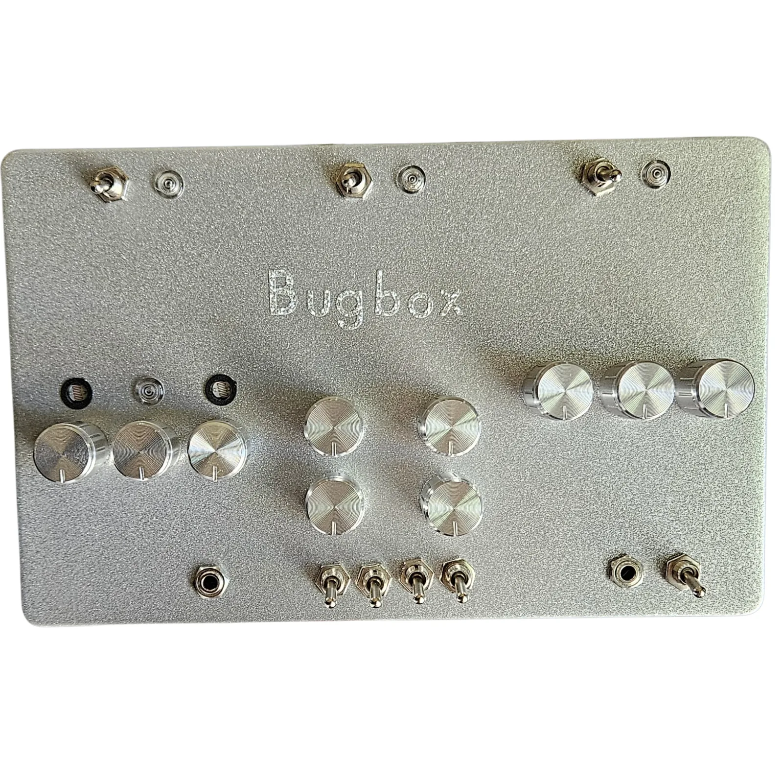
My Opto Duet CV, Cicada NAND and Dragonfly VCO boards in one silver 1590DD. Each board has its own power toggle and light, one DC jack feeds all three, and their outputs are wired together into one jack. This page is the box: the drill template, the power and the output. Each board's own guide has its parts list and how to build it.
What you'll need
tap to expand / collapse
The three boards, each built from its own guide. Leave their power, output and DC parts off: the box shares those, and this list has them.
- 1× Opto Duet CV PCB, built: Opto Duet CV
- 1× Cicada NAND PCB, built: Cicada NAND
- 1× Dragonfly VCO PCB, built: Dragonfly VCO
- 1× 1590DD enclosure, 188 by 120 mm on its face
- 1× DC jack for a 9V supply, center negative
- 3× SPST toggles for power, one per board
- 3× 5 mm LEDs for the power lights, each with a series resistor, 2K2 to 4K7 on 9V. Spot it: the long leg is +
- 1× 3.5 mm mono jack for the mixed output
- The boards' own jacks and toggles: the Opto Duet's PITCH CV jack, the Cicada's four gate toggles, the Dragonfly's MODE toggle and IN / CV jack
- Hookup wire
The drill template
The template puts each board's own 125B holes in a column, three columns side by side on the 1590DD's face, with each board's power toggle and light in a strip along the top. The DC jack and the output go on the top wall.
Print at 100% / “Actual size”, never “Fit to page”, and check the bar measures exactly 4″ before you touch a drill.
I drilled my Bugbox from this sheet. Its Cicada's pots ended up on wires, mounted in the face and wired back to the board, and the board still sits where the sheet draws it. Fit your pots to each board and offer the boards up to the sheet before you make a hole.
Power: one jack, three switches
Each board's power header is the same: DC+, SW and GND. In the Bugbox the one DC jack feeds all three.
- The DC jack's + lug goes to one lug of each of the three power toggles. On a center-negative supply the + is the jack's sleeve lug.
- Each toggle's other lug goes to SW on its own board.
- The DC jack's - lug, its center pin, goes to GND on all three boards.
- Each power light goes from its toggle's SW lug, through its resistor, to GND, long leg toward the toggle, so it lights when that board is on.
Each board keeps its own reverse-polarity diode, so a supply plugged in the wrong way around is stopped at all three.
The output: three into one
The three OUT pins are wired together to the output jack's tip, and the three output GND pins to its sleeve. There are no mixing resistors in mine: they are wired straight together. The Opto Duet's LEVEL and the Dragonfly's VOL set how much of each you hear, and the Cicada's gate toggles bring its voices in and out.
Putting it together
- Build the three boards from their own guides, and test each one on its own before it goes in the box.
- Print the template and check the 4″ bar. Offer each board, pots fitted, up to its column.
- Drill. Pilot at 3 mm, open up, deburr, then blow every chip of swarf out of the box.
- Boards first. Solder a wire to every header pin you use, long enough to reach its part, and put the boards in on their pots. The DC jack and the output pass behind the boards, so they go on the top wall after the boards are in.
- The face parts: the power strip, the gate toggles, MODE and the two CV jacks. Then the power and the output, as above.
Things to try
- A resistor in each output before they meet, 10K is a common choice, is the usual passive mix. Untested: mine has none, and works.
The three boards are mine, and so is the box. Each board's guide credits its circuit.