Cicada NAND PCB
CD4093 on a 56 by 78 mm printed board · By Onion Madder · Mess O' Pedals
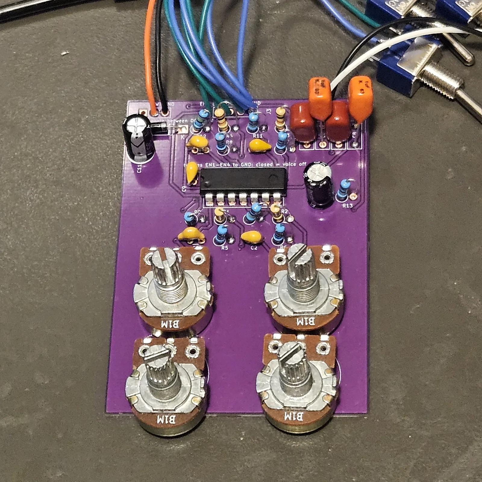
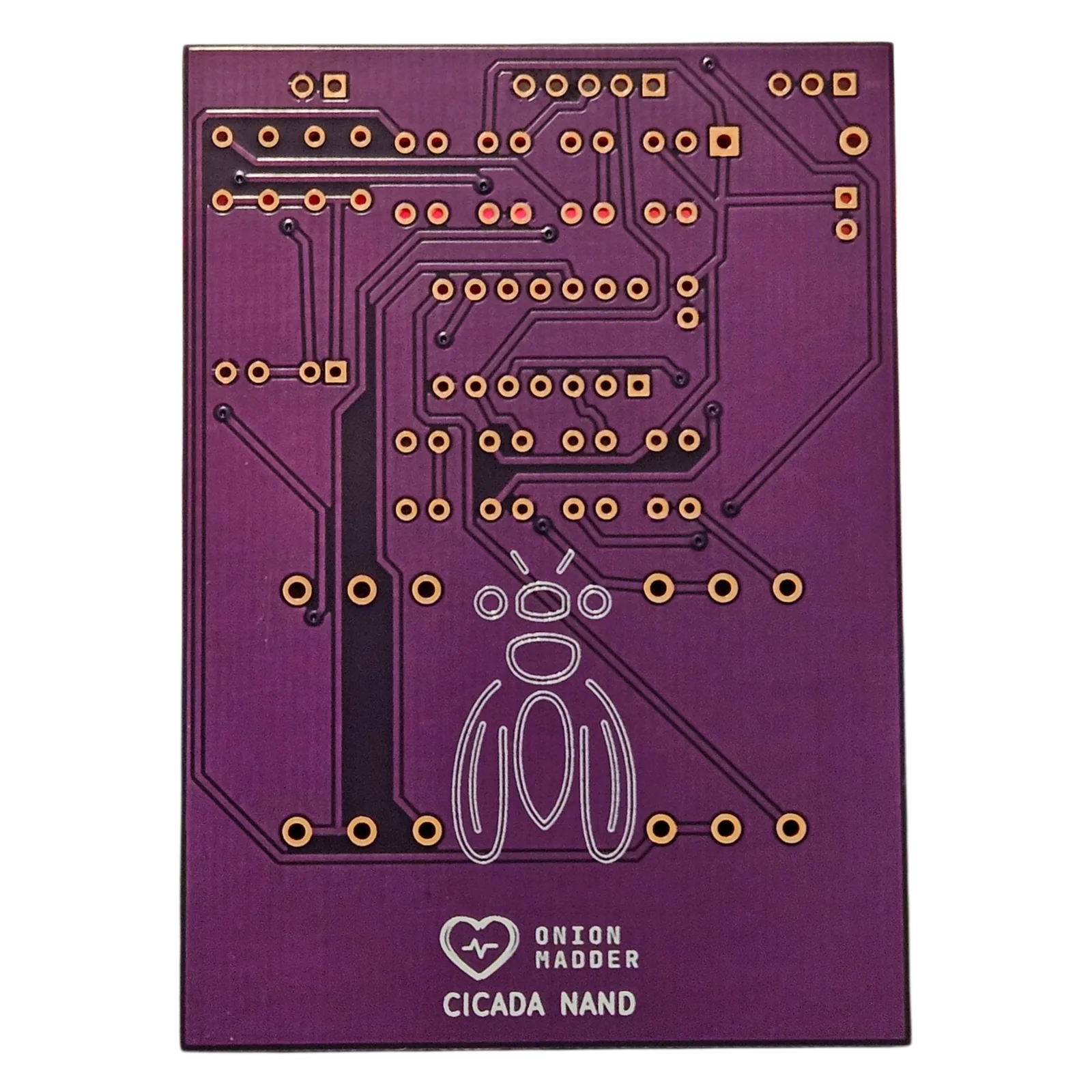
The Cicada NAND on a printed board. Four voices from one CD4093, each a Schmitt NAND gate with its own timing cap a decade apart from its neighbors, its own PITCH pot on the board and its own gate on a header, all mixed to one output.
What you'll need
tap to expand / collapse
30 parts on the board. The numbers in brackets are the ones printed beside each part's outline. ↓ Download the parts list (PDF), one page to print for the bench and tick off as each part goes in.
- 1× CD4093 (U1) - spot it: CD4093 printed on top, a notch or dot marks pin 1. Four Schmitt NAND gates, one per voice
- 4× 1M resistor (R9, R10, R11, R12) - spot it: bands brown-black-green. The gate pull-ups. Each holds a voice on until something pulls it low
- 1× 1M resistor (R13) - spot it: bands brown-black-green. The output pull-down
- 4× 10K resistor (R5, R6, R7, R8) - spot it: bands brown-black-orange. The mixer, one per voice
- 4× 1K resistor (R1, R2, R3, R4) - spot it: bands brown-black-red. One per pot, in series and not optional: at zero ohms the gate's output ties straight to its own input and the voice dies into a short
- 1× 1nF ceramic (C3) - spot it: printed 102. Voice 3's timing cap
- 1× 10nF ceramic (C1) - spot it: printed 103. Voice 1's timing cap
- 1× 100nF ceramic (C2) - spot it: printed 104. Voice 2's timing cap
- 1× 1 µF ceramic (C4) - spot it: printed 105. Voice 4's timing cap, the lowest
- 1× 100nF ceramic (C9) - spot it: printed 104. Across the supply
- 4× 1 µF film or other non-polarized cap (C5, C6, C7, C8) - spot it: a small box, printed 105. The mixer, one per voice. Non-polarized; the board has a box footprint for them
- 1× 10 µF electrolytic (C10) - spot it: a can with a stripe down the minus leg. The long leg goes in the square pad, marked +. The output cap
- 1× 100 µF electrolytic (C11) - spot it: a can with a stripe down the minus leg. The long leg goes in the square pad, marked +. Across the supply
- 1× 1N5817 (D1) - spot it: black body, gray band. The band goes to the square pad, the end the board marks with a band and a K. Reverse-polarity protection on the supply
- 4× B1M pot, 16 mm, board mount (RV1, RV2, RV3, RV4) - PITCH 1 to 4. Spot it: the B is the linear taper.
- 1× Cicada NAND PCB
Off the board
- 1× DC jack and a 9V supply, center negative
- 1× SPST toggle for power, between the DC jack's + lug and SW
- 4× SPST toggles for the gates, if you want them. A touch plate or a photocell to GND works on the same pins
- 1× 3.5 mm mono jack for the output
- Hookup wire for the headers
What is different from the stripboard
- Three parts the stripboard does not have: D1, a 1N5817 in the supply lead against a supply plugged in the wrong way around, C11, a 100 µF across the supply, and R13, a 1M from the output to ground so the output cap does not sit charged with nothing plugged in.
- The four PITCH pots are on the board, each a variable resistor over its 1K, exactly as the stripboard guide wires them off it.
- The gates are on J3. Each EN pin is held high by its 1M, so every voice plays with nothing connected. A toggle from an EN pin to GND turns that voice off when it is closed.
The headers
Everything that leaves the board leaves from a header along the top edge, and each one has its pins labeled on the board.
| Header | Pins | Goes to |
|---|---|---|
| J1 | DC+ / SW / GND | Power, wired the usual way: the DC jack's + lug to one lug of the power toggle, the toggle's other lug to SW, and the jack's - lug to GND. On a center-negative supply the + is the jack's sleeve lug and the - is its center pin. SW is the board's power input, through D1, which guards against a supply plugged in the wrong way around. DC+ connects to nothing on the board: it is a spare pad to join the jack's + and the toggle on, if that is easier, and it can stay empty. The note printed on the board, power toggle between DC+ and SW, means the same thing |
| J3 | EN1 to EN4 / GND | The gates, one per voice. A toggle from each EN pin to GND: closed is that voice off. Leave a pin bare and its voice just plays |
| J2 | OUT / GND | The output jack: tip to OUT, sleeve to GND |
Building it
- Lowest parts first, so the board sits flat on the bench while you solder: resistors, then the diodes, then the small ceramic caps.
- Before any chip goes in, power it up once. Fit the DC jack and the power toggle on their header, switch on, and put the meter's black probe on a GND pin and the red one in U1's pin 14 hole, from the top. You want the supply, less about 0.2V for the diode. Nothing there, or the full supply with the leads reversed, means look at the diode's band before going on. Switch off.
- The chips (U1), soldered straight in. Pin 1 goes to the square pad, the end the board marks with a notch.
- The electrolytics, long leg in the square pad, marked +, then the LEDs and photocells.
- The pots last. Push each one flush to the board and keep its shaft square before you solder the first leg; a crooked pot is a hole that will not line up.
- Or the pots on wires. The board is drawn for 16 mm board-mount pots, but depending on the pots you have, they may not sit right on it: different legs, a different body, or a shaft that will not reach the face. Then put them on short wires, one from each pad to the lug in the same place, so the knob still turns the right way. In my Bugbox, this board's pots ended up on wires. Off the pots, the board no longer hangs on them, so it needs another way to sit in the box, and the pot holes are yours to place.
- Into the box, board first. Solder a wire to every header pin you use, long enough to reach its wall, and put the board in on its pots before anything goes on the walls: the wall parts pass behind the board, so they go in after it. Then fit them and wire them up as the table above says.
The board hangs about 12 mm behind the face on its pot bodies, so anything on it taller than that, usually an electrolytic, gets laid over flat before the board goes in.
Print at 100% / “Actual size”, never “Fit to page”, and check the bar measures exactly 4″ before you touch a drill.
Nobody has drilled this one yet. Fit the pots to the board, offer the board up to the sheet, and check it against your own parts before you make a hole.
Circuit from the Cicada NAND stripboard guide, every part value taken from its layout file. Board by Onion Madder.