Grub Divider Mk II
Seven octaves down a CD4024, with a preamp in front so anything can drive it · By Onion Madder · Mess O' Pedals
The Grub Divider counts edges, so it wants something that swings hard: my Atari Punk Console drives it beautifully, and a guitar on its own barely makes it twitch. This board puts a TL072 preamp in front of the Grub to bring any signal up to where the counter picks it up. A GAIN knob sets how much, and a TRACK switch makes it follow the note more cleanly. The Grub itself is the board I built, unchanged.
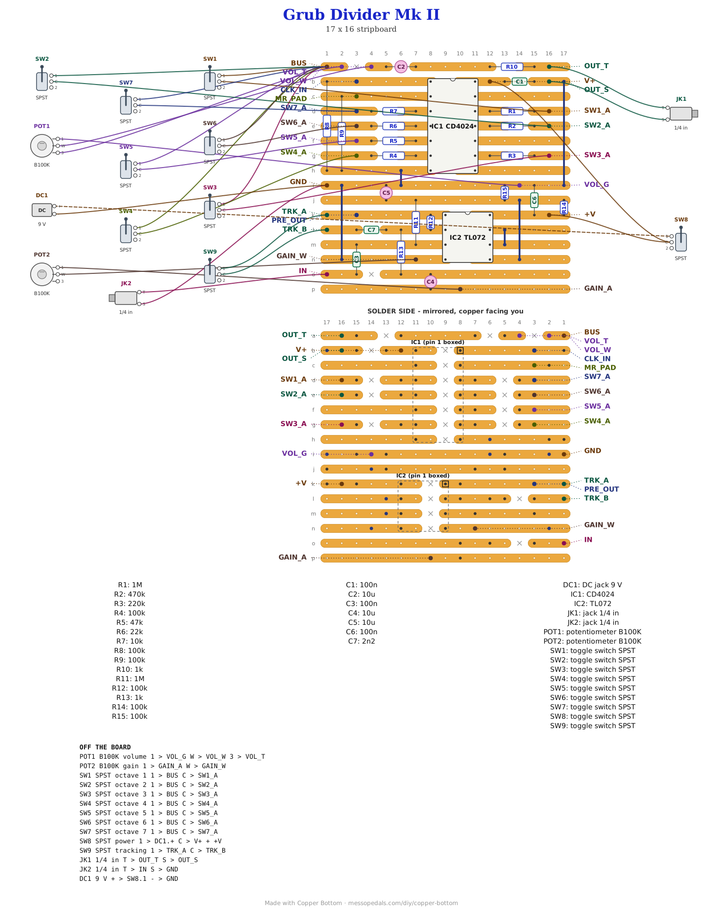
What you'll need
tap to expand / collapse
Twenty-seven parts on the board, counting five wire links, and fourteen off it. The Grub half keeps the Grub Divider's parts and reference numbers.
The Grub, strips a to i
- 1× CD4024 seven-stage binary counter, 14-pin DIP (IC1) - spot it: CD4024 printed on top, notch marks pin 1
- The weighted ladder, one resistor per octave and every value different (R1 to R7): 1M, 470K, 220K, 100K, 47K, 22K, 10K. They are what make this a mixer instead of a selector
- 2× 100K (R8, R9) - spot it: bands brown-black-yellow. The clock and reset pull-downs
- 1× 1K on the output (R10), 1× 100n (104) across the supply (C1), 1× 10 µF electrolytic to block the DC (C2)
- 2× wire links (J1, J2)
The preamp, strips j to p
- 1× TL072 dual op-amp, 8-pin DIP (IC2) - spot it: TL072 printed on top, a notch or a dot at pin 1. Use a socket: any dual op-amp with the standard pinout goes in the same holes, and trying a few is half the point
- 1× 1M resistor (R11) - spot it: bands brown-black-green. Holds the input at the half rail, and is most of what the input looks like to a guitar
- 3× 100K resistor (R12, R14, R15) - spot it: bands brown-black-yellow. R12 is the feedback, the one that sets the most gain; R14 and R15 make the half rail. All three stand on end
- 1× 1K resistor (R13) - spot it: bands brown-black-red. The floor under the GAIN pot
- 1× 100nF film (C3) - spot it: a small box, printed 104. The input cap
- 1× 100nF ceramic (C6) - printed 104. The TL072's supply decoupling
- 1× 2.2nF ceramic (C7) - spot it: printed 222. The tracking cap. It lies along strip l, across a cut
- 2× 10 µF electrolytic (C4, C5) - spot it: a small can, stripe on the minus leg. C5 holds the half rail still; C4 sits in the gain leg so the output idles at the half rail
- 3× wire links (J3 to J5). J3 is the long one down the left, the preamp's ground
- 1× DIP-8 socket
- 1× stripboard, 16 strips × 17 holes or larger
Off the board
- 1× B100K linear pot - GAIN. Wired as a variable resistor: one outer lug to GAIN_A, the wiper to GAIN_W, the third lug left empty. Its 1K floor is on the board
- 1× B100K linear pot - VOLUME, all three lugs, as on the Grub
- 7× SPST switches, one per octave
- 1× SPST switch - TRACK, across TRK_A and TRK_B
- 2× 1/4″ jack - the input, now into IN, and the output
- 1× DC jack, 9 V, or a battery snap
- Two wires between pads: PRE_OUT to CLK_IN, and +V to the power toggle's common beside V+
- 1× momentary switch between MR_PAD and V+ for a retrigger - optional, the same as on the Grub
- An SPST toggle for power, in the positive supply lead between the DC jack or battery and the board's V+ pad. Not in the layout file - it is off the board, and every build on this shelf gets one
The layout file is the guide
Like every layout on this shelf, the build document for this one is the file itself: ↓ Download Grub_Divider_MkII.json - import it into Copper Bottom and the editor gives you the board picture, the placement walkthrough, the electrical checks and a printable build sheet, all from the same file. No coordinates are written out on this page on purpose: the editor is the viewer, and a number typed twice is a number that can drift.
Two boards on one piece of copper. Strips a to i are the Grub Divider as I built it, not moved by a hole. The preamp shares only the ground strip, i, through J3. Its supply comes in on its own +V pad and its output leaves on PRE_OUT, so the only joins between the two halves are wires you add, and a bypass switch can go between them if you want a raw input as well.
The netlist
Quoted verbatim from the layout file, and emitted from the copper rather than typed
beside it - so checking the board against it can only pass. The preamp is
VREF, IN_P, IN_N and PRE_OUT; everything
from BUS to IC1_NC_3 is the Grub.
The off-board wiring
Twenty-four pads leave the board.
| Pad | Goes to |
|---|---|
| V+ / +V / GND | The supply. DC jack positive to the power toggle, and the toggle's common to both V+ and +V - one feeds the Grub, the other the preamp. Negative to GND, which is also both jack sleeves |
| IN | The input jack's tip. Anything: a guitar, a synth, a phone |
| PRE_OUT / CLK_IN | A wire between them. PRE_OUT is the preamp's output and CLK_IN is the counter's input. Put a switch here instead of a wire if you want to pick the preamp or a raw jack |
| GAIN_A / GAIN_W | The GAIN pot, a variable resistor: one outer lug to GAIN_A, the wiper to GAIN_W, which is ground. At zero ohms it is the most gain, about 101, and at the full 100K about 2; which end of the turn that is depends on which outer lug you use |
| TRK_A / TRK_B | The TRACK switch. Closed, it puts C7 across the feedback resistor |
| SW1_A … SW7_A / BUS | The seven octave switches, as on the Grub. Each SW pad is one octave through its own weighted resistor; each switch's other side goes to BUS |
| VOL_T / VOL_W / VOL_G | Volume pot, all three lugs |
| OUT_T / OUT_S | Output jack, tip and sleeve |
| MR_PAD | The Grub's master reset, held low by R9. A momentary switch between MR_PAD and V+ is a retrigger, or leave it empty |
Before the chips go in
Four meter checks, and they find most of what a preamp can get wrong.
- Socket empty, power on: strip j reads about half the supply, near 4.5 V on 9 V. If it does not, R14, R15 or C5 is the place to look.
- Still empty: pin 8 of the socket reads the full supply and pin 4 reads 0 V. If pin 8 is dead, the +V wire is the one missing.
- TL072 in, nothing plugged in: PRE_OUT sits near the half rail.
- A guitar in, GAIN turned up: PRE_OUT swings up and down around the half rail and the octaves come in. If they cut in and out at full gain, the op-amp is not swinging far enough to cross the counter's trigger points - try another op-amp in the socket before anything else.
How it works, in one breath
The Grub's counter only moves when its input crosses a trigger point near the middle of the supply, so a weak signal does nothing and a strong square does everything. The preamp is one half of the TL072 as a non-inverting amplifier around a half rail: R14 and R15 make about 4.5 V, R11 holds the input there, and the signal comes in through C3. R12 against R13 plus the GAIN pot sets how much it is multiplied, from about 2 to about 101, and C4 in the gain leg keeps the output sitting at the half rail with nothing playing.
At low gain only the loudest peaks reach the trigger points, which is the Grub's own sputtery behavior. Turn it up and more of the signal crosses them, until near the top the op-amp is clipping at both ends and the counter sees a clean square. PRE_OUT goes straight into the counter with no cap, on purpose: a cap would center the swing on ground, and a swing centered on ground never reaches the upper trigger point.
A guitar note carries strong harmonics, and some of them cross the trigger point more than once a cycle, which is part of why octave dividers glitch. TRACK puts C7 across R12, which turns the gain down above about 720 Hz and favors the fundamental. Off, the glitches are back. The other half of the TL072 is parked as a follower on the half rail, doing nothing.
The numbers are arithmetic. Gain is 1 + 100K over (1K + the pot). The tracking corner is 1 over 2π times 100K times 2.2nF, about 720 Hz, and 2.2nF is a starting value: bigger tracks lower notes more cleanly and dulls the top. A TL072's output gets to within about 1.5 V of each rail; whether that crosses the CD4024's trigger points on 9 V is the first thing to check on the bench.
Things to try
None of these have been tried, because the preamp has not been built.
- Swap the op-amp. Any dual with the standard pinout fits the socket. An LM358 gets closer to ground at the bottom of its swing; an NE5532 is faster.
- Change C7. 4.7nF for bass, 1nF to keep more top.
- A bypass switch between PRE_OUT and a second jack straight into CLK_IN, so the Grub can still take an APC raw.
- Jumper an SW pad to MR_PAD for odd divisions, the Grub's own trick.
The divider is my Grub Divider, after the classic 4024 octave divider. The preamp is the non-inverting op-amp stage in every op-amp book. The layout and the tracking switch are mine, drawn in Copper Bottom, and so is anything wrong with them.