Octave Avalanche
One pitch knob, seven toggles, a wall of octaves · By Onion Madder · Mess O' Pedals
One oscillator and a binary counter. The 40106 runs high, up past hearing at the top of the knob, and clocks a CD4040, whose outputs are that clock divided by two, four, eight and so on down the chain. Every output is a square wave exactly one octave below the one before it. Seven of them come out through resistors to seven toggles, and the toggles feed one mixing node, so any set of octaves you like plays at once, from a single sub-bass to all seven stacked. One pitch knob moves the whole stack together, because it is all one clock.
What you'll need
tap to expand / collapse
Sixteen parts on the board plus the links, and twelve off it, eight of them toggles.
- 1× CD40106 hex Schmitt inverter, DIP-14 (U1) - spot it: fourteen legs, the number printed on top, a notch at one end. One gate is the oscillator; the other five are tied off. Fit a socket
- 1× CD4040 12-stage binary counter, DIP-16 (U2) - spot it: sixteen legs, notch at one end. Twelve flip-flops in a chain, of which this board uses the first seven. Fit a socket
- 1× 1N5817 Schottky (D1) - spot it: fat black body, a gray band at one end. Reverse-polarity protection on the supply
- 1× 100K resistor (R10) - spot it: bands brown-black-yellow. Ties the output to ground so the level pot has something to sit on
- 7× 47K resistor (R2, R3, R4, R5, R6, R7, R8) - spot it: bands yellow-violet-orange. One per voice, from each 4040 output to its toggle. They are the mixer: seven of them into R9 is a passive summer, and equal values mean equal octaves
- 1× 10K resistor (R9) - spot it: bands brown-black-orange. The bottom of the mixer, from the MIX node to ground
- 1× 1K resistor (R1) - spot it: bands brown-black-red. In series with the pitch pot, so the oscillator can never see zero ohms
- 1× 10nF ceramic (C1) - spot it: printed 103. The timing cap, pin 1 to ground. Bigger is lower
- 2× 100nF ceramic (C4, C5) - spot it: printed 104. One decoupling cap per chip
- 1× 1 µF electrolytic (C2) - spot it: a small can with a stripe down one side; the stripe leg is the negative one. The output coupling cap. Stripe toward the level pot
- 1× 100 µF electrolytic (C3) - spot it: a small can with a stripe down one side; the stripe leg is the negative one. The supply reservoir. Stripe to ground
- 10× wire links - offcuts of component leg
- 1× DIP-16 socket and 1× DIP-14 socket
Off the board
- 1× B500K linear pot - master pitch. A variable resistor: lug 3 to P, wiper to RATE, wiper jumpered to lug 1. The 1K it needs in series is R1, on the board
- 1× A100K log pot - level. Lug 3 to OUT, lug 1 to GND2, wiper to the output jack tip
- 7× SPST toggles - the voices, 1 to 7. One lug of each to its own pad, S1 to S7; the other lugs all daisy-chained together and into MIX
- 1× 1/4 inch jack - out. Tip to the level wiper, sleeve to GND2
- 1× DC jack, 9 V center negative
- An SPST toggle for power, in the positive supply lead between the DC jack and the board's +9V pad. Every build on this shelf gets one, and the drawing above shows it
The layout file is the guide
Like every layout on this shelf, the build document for this one is the file itself: ↓ Download Octave_Avalanche.json - import it into Copper Bottom and the editor gives you the board picture, the placement walkthrough, the electrical checks and a printable build sheet, all from the same file. No coordinates are written out on this page on purpose: the editor is the viewer, and a number typed twice is a number that can drift.
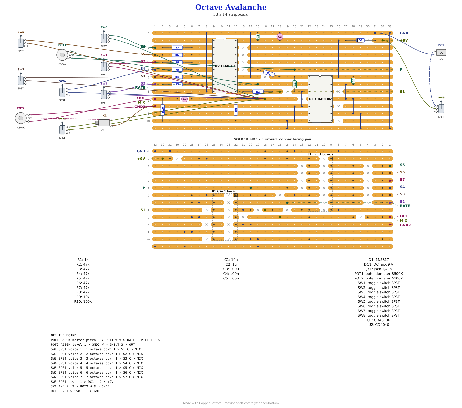
Two ground strips, one net. Strip a along the top carries the GND pad; GND2 sits at the bottom of the left edge, and links join the two. Six of the seven 47K resistors stand in a column to the left of the 4040, each beside the pin it serves, and the S pads run down the left edge in the order the chip puts its outputs, which is not 1 to 7 - read the pad names, not the row order.
The netlist
My script wrote this from the design and the board was checked against it in Copper Bottom: every connection it names is on the board and nothing on the board is missing from it. The lines that matter are OSC, the one oscillator output feeding the 4040's clock, and Q1 to Q7, one per voice, each a counter pin and one resistor. The 4040's pins are not in order, and Q7 on pin 4 next to Q4 on pin 5 is the one to get right.
The off-board wiring
Fourteen pads leave the board: the pitch pot, the level pot, seven toggles, the mix node they share, the jack and the supply.
| Pad | Goes to |
|---|---|
| P / RATE | The B500K pitch pot. Lug 3 to P, wiper to RATE, wiper jumpered to lug 1. R1 is its 1K floor |
| S1 to S7 | One lug of each voice toggle. S1 is one octave down, S7 is seven. On the board they are not in that order, so read the pad label |
| MIX | The other lug of all seven toggles, daisy-chained. Every closed toggle adds its octave here |
| OUT | Level pot lug 3. The wiper goes to the output jack tip, and lug 1 to GND2 |
| GND2 | Level pot lug 1 and the jack sleeve. Same net as GND |
| +9V / GND | The supply, through the power toggle. DC jack positive to the toggle and the toggle to +9V; negative to GND |
How it works, in one breath
One gate of the 40106 is the oscillator: its output goes through R1 and the pitch pot back to its own input, with C1 to ground, so it charges and discharges between the gate's two thresholds and puts out a square wave. With 10n and a 500K pot that wave runs from somewhere in the low hundreds of hertz at the bottom of the knob to well past hearing at the top, and past hearing is fine, because nobody listens to it directly. It clocks the 4040. A 4040 is twelve flip-flops in a row, each one toggling when the one before it falls, so Q1 is the clock divided by two, Q2 by four, Q3 by eight, down to Q7 at one 128th: seven square waves, each exactly an octave below the last, all locked to the same edge.
Each of the seven goes through a 47K resistor to a toggle, and the toggles' other lugs all meet at MIX, where R9 to ground makes a passive mixer. Close one toggle and you hear one octave; close three and you hear a chord of octaves, which on square waves is a thick, buzzy thing with a lot of beating where the edges line up. Turn the pitch knob and all seven move together. C2 blocks the DC and the level pot sets how much of it leaves. That is what the schematic does, and it is a read of the circuit, not of a build; how the stacks actually sound with equal resistors, and whether the top voices want quieting, is the bench's to say.
Things to try
None of these have been tried, because none of this has. They are the obvious knobs.
- Unequal resistors. 47K on the low voices and 100K on the high ones tames the fizz at the top
- Change C1 to 47n and the whole stack drops a couple of octaves, into territory where Q1 is already a bass note
- Bring out Q8 to Q12. Pins 13, 12, 14, 15 and 1 are five more octaves down, into clicks. A twelfth toggle is a slow pulse
- Clock it from outside. Lift R1 and feed the XOR Cross-Mod into pin 10 of the 4040 instead, and the octaves follow that
A 40106 into a 4040 with a resistor per output is the standard sub-octave idiom of the Lunetta crowd, and it belongs to everyone who has ever built one. Seven toggles into one node, and the layout, are mine and so is anything wrong with them.