APC Grub
An Atari Punk Console into seven octaves of divider, on one board · By Onion Madder · Mess O' Pedals
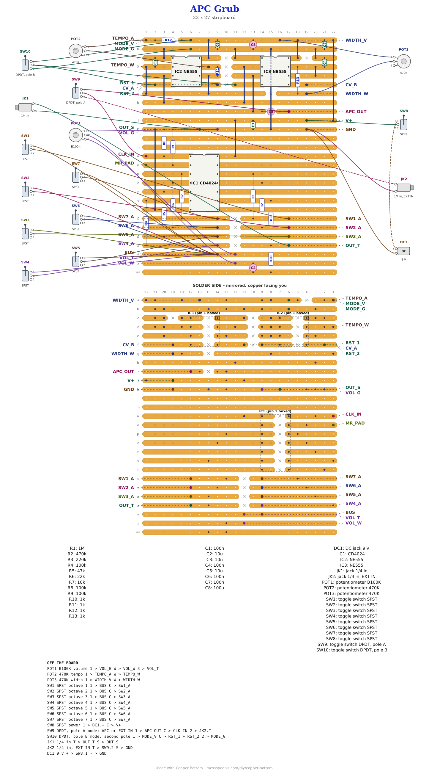
An Atari Punk Console into the Grub Divider is the patch I like best: it goes robotic and chirpy, and which of those depends on how the switches are flipped. This board puts the two together. Two 555s make the APC, a CD4024 divides it into seven octaves down, and seven switches pick which octaves sit in the mix. A MODE toggle hands the divider to an EXT IN jack instead and stops the APC dead, so the Grub still works on anything else you feed it.
What you'll need
tap to expand / collapse
Thirty-six parts on the board, counting fifteen wire links, and fourteen off it. The Grub half is exactly the Grub Divider's parts, with the same reference numbers.
- 2× NE555 timer, 8-pin DIP (IC2, IC3) - spot it: NE555 or just 555 printed on top, a notch or a dot at pin 1. IC2 is the oscillator, IC3 the one-shot it triggers. Sockets are worth it
- 1× CD4024 seven-stage binary counter, 14-pin DIP (IC1) - spot it: CD4024 printed on top, notch marks pin 1
- The weighted ladder, one resistor per octave and every value different (R1 to R7): 1M, 470K, 220K, 100K, 47K, 22K, 10K. They are what make this a mixer instead of a selector - get one wrong and that octave is too loud or inaudible
- 2× 100K resistor (R8, R9) - spot it: bands brown-black-yellow. The clock and reset pull-downs. R8 is what the APC lands on
- 4× 1K resistor (R10 to R13) - spot it: bands brown-black-red. R10 is the Grub's output. R11 is the APC oscillator's 1K, Paul's value. R12 and R13 are the stops, one in series with each 470K pot, so a knob turned to the end never puts a 555's pin 7 straight onto the supply
- 1× 10nF ceramic (C3) - spot it: printed 103. The oscillator's timing cap
- 4× 100nF ceramic (C1, C4, C6, C7) - spot it: printed 104. C4 is the one-shot's timing cap; the other three sit across the supply, one by each chip
- 2× 10 µF electrolytic (C2, C5) - spot it: a small can, stripe on the minus leg. C5 couples the APC into the divider and C2 blocks the DC on the way out
- 1× 100 µF electrolytic (C8) - across the supply, for the current two 555s pull every time they switch. Stripe to ground
- 15× wire links (J1 to J15) - offcuts of component leg. J15 runs under IC3, down the cut column, so it goes in before the chip or its socket
- 1× stripboard, 27 strips × 22 holes or larger
Off the board
- 2× 470K pot - TEMPO and WIDTH, Paul's values. Each one wired as a variable resistor: one outer lug and the wiper, the third lug left empty. Their 1K stops are on the board
- 1× B100K linear pot - VOLUME, all three lugs
- 1× DPDT toggle, on-on - MODE. One pole picks what the divider hears, the other runs or stops the APC
- 7× SPST switches, one per octave
- 2× 1/4″ jack - EXT IN and the output
- 1× DC jack, 9 V, or a battery snap
- 1× momentary switch between MR_PAD and V+ for a retrigger - optional, the same as on the Grub
- An SPST toggle for power, in the positive supply lead between the DC jack or battery and the board's V+ pad. Not in the layout file - it is off the board, and every build on this shelf gets one
The layout file is the guide
Like every layout on this shelf, the build document for this one is the file itself: ↓ Download Apc_Grub.json - import it into Copper Bottom and the editor gives you the board picture, the placement walkthrough, the electrical checks and a printable build sheet, all from the same file. No coordinates are written out on this page on purpose: the editor is the viewer, and a number typed twice is a number that can drift.
Two boards in one. Strips a and b are V+ and ground for the APC, and the two 555s stand side by side under them. Strips g, h and i carry the joins the chips cannot make on their own strips: the oscillator's timing node, the clock from one 555 to the other, and the output on its way to C5. Everything from strip j down is the Grub Divider as I built it, not moved by a hole, and J14 and J15 are the only copper joining the two: one for V+, one for ground.
The netlist
Quoted verbatim from the layout file, and emitted from the copper rather than typed
beside it - so checking the board against it can only pass. What it is for is carrying the
circuit somewhere else, and telling you what each strip is doing while you stare at it. The
APC is OSC_TIM, OSC_DIS, CLOCK and
SHOT_TIM; everything from CLK_IN down is the Grub.
The off-board wiring
Twenty-eight pads leave the board: three knobs, the mode toggle, seven octave switches, two jacks and the supply, plus two pads you can leave empty.
| Pad | Goes to |
|---|---|
| V+ / GND | The supply, through the power toggle. DC jack positive to the toggle and the toggle to V+; negative to GND, which is also both jack sleeves |
| TEMPO_A / TEMPO_W | The TEMPO pot, a variable resistor: one outer lug to TEMPO_A, the wiper to TEMPO_W, the third lug empty. TEMPO_A reaches V+ through R12, the stop |
| WIDTH_V / WIDTH_W | The WIDTH pot, the same way round: one outer lug to WIDTH_V, which is V+, the wiper to WIDTH_W, which reaches the one-shot through R13 |
| APC_OUT / CLK_IN | MODE, the first pole. Common to CLK_IN. One throw to APC_OUT, the APC after C5; the other to the EXT IN jack's tip. With nothing plugged into EXT IN the divider's input still sits on R8 to ground, so it never floats |
| RST_1 / RST_2 / MODE_V / MODE_G | MODE, the second pole. Its common goes to both RST pads, pin 4 of each 555. The throw on the same side as APC_OUT goes to MODE_V and the other to MODE_G. So when the divider is listening to the APC the 555s run, and when it is listening to EXT IN they are held in reset and make nothing, not even a whine on the supply |
| SW1_A … SW7_A / BUS | The seven octave switches. Each SW pad is one octave arriving through its own weighted resistor; each switch's other side goes to the BUS pad, which is where they all sum |
| VOL_T / VOL_W / VOL_G | Volume pot, all three lugs |
| OUT_T / OUT_S | Output jack, tip and sleeve |
| MR_PAD | The Grub's master reset, held low by R9. A momentary switch between MR_PAD and V+ is a retrigger, or leave it empty |
| CV_A / CV_B | Pin 5 of each 555, left open as Paul has them. Leave them empty, or a 100K from a CV jack tip to bend the oscillator (CV_A) or the one-shot (CV_B) - untested |
How it works, in one breath
The APC is two 555s. IC2 runs free, a square wave whose speed is the TEMPO knob. Every time it falls it triggers IC3, a one-shot that puts out one pulse as long as the WIDTH knob says. When the pulse is shorter than the gap between triggers you hear the oscillator; when it is longer, IC3 is still busy when the next trigger arrives and ignores it, so the pitch jumps down in steps instead of sliding. That stepping is the APC's whole sound.
The CD4024 counts edges. Its first output changes on every second edge, an octave down; each output after it halves that again, seven octaves in all, and the weighted resistors bring them into one bus with the low ones strongest. So every step the APC takes, every octave you have switched on takes it too, lower down. The APC reaches the counter through C5, as it does on my bench: the cap takes the DC off the pulses, so what the counter sees depends on how wide they are as well as how often they come.
Three pins on the CD4024 go nowhere and that is correct. Pins 8, 10 and 13 are no-connects, and Copper Bottom's checks leave them alone. Pin 5 of each 555 is the CV pad and may be left open; the datasheet's 10nF to ground is only needed on a noisy supply.
Things to try
None of these have been tried on this board, because this board has not been built.
- Leave MODE on the APC and play the switches. That is the patch this board was drawn for.
- EXT IN from another oscillator - the Cicada or the 555 theremin - is the Grub on its own, with the APC silent.
- An LFO into CV_A through 100K, the Dual-Wave LFO say, makes the APC wander and the whole octave stack with it.
- Jumper an SW pad to MR_PAD for odd divisions and looping patterns, the Grub's own trick.
The Atari Punk Console is Forrest Mims' Stepped Tone Generator. The part values on the APC half are Paul Stevenson's, from his two-555 Atari Punk Console layout on Paul In The Lab, which I have built many times; the 1K stops and the decoupling are mine. The divider is my Grub Divider, after the classic 4024 octave divider. The layout and the mode switching are mine, drawn in Copper Bottom, and so is anything wrong with them.