Grub Divider
Seven octaves down a CD4024, switched into one bus, drawn in Copper Bottom · By Onion Madder · Mess O' Pedals
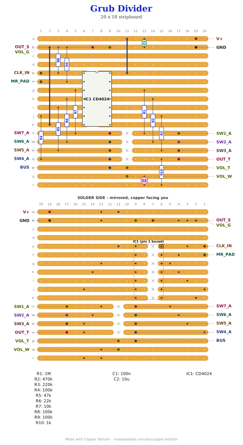
The Dead-Bug Grub, soldered and given switches. A CD4024 is seven flip-flops in a chain: feed a square wave into one end and every output along it is another octave down. This board brings all seven out through weighted resistors onto one bus, each on its own switch - so you are not choosing an octave, you are mixing them, and the weighting means the low ones sit under the high ones instead of burying them.
What you'll need
tap to expand / collapse
- 1× CD4024 seven-stage binary counter, 14-pin DIP - spot it: CD4024 printed on top, notch marks pin 1
- The weighted ladder, one resistor per octave and every value different: 1M, 470K, 220K, 100K, 47K, 22K, 10K. They are what make this a mixer instead of a selector - get one wrong and that octave is too loud or inaudible
- 2× 100K - the clock and reset pull-downs
- 1× 1K on the output, 1× 100n (104) across the supply, 1× 10 µF electrolytic to block the DC
- 1× stripboard, 9 strips × 17 holes or larger, and wire for two links
Off the board
- 7× SPST switches, one per octave
- 1× 100K pot, off-board - the volume
- 1× 9V supply, and something to divide - this makes no sound on its own
- 2× 1/4″ jack - one for the clock input, one for the output
- 1× momentary switch between MR_PAD and V+ for a retrigger - optional
- An SPST toggle for power, in the positive supply lead between the DC jack or battery and the board's supply pad. Not in the layout file - it is off the board, and every build on this shelf gets one
The layout file is the guide
Like the 555 theremin and the Opto Duet, the build document for this one is the file itself: ↓ Download Grub_Divider.json - import it into Copper Bottom and the editor gives you the board picture, the placement walkthrough, the electrical checks and a printable build sheet, all from the same file. No coordinates are written out on this page on purpose: the editor is the viewer, and a number typed twice is a number that can drift.
The netlist
Quoted verbatim from the layout file. It was written from the board, so checking the board against it can only pass - what it is for is carrying the circuit somewhere else, and telling you what each strip is supposed to be doing while you stare at it.
The off-board wiring
Seventeen pads leave the board.
| Pad | Goes to |
|---|---|
| V+ / GND | The supply, 3V to 15V |
| CLK_IN | The thing to divide. A square wave from any of the oscillators on this site - the Cicada or the 555 theremin will drive it happily. Held down by its own 100K, so an unplugged input is quiet rather than random |
| MR_PAD | Master reset. Held low by a 100K, so the counter free-runs; touch it high and the chain restarts from the top. A momentary switch between MR_PAD and V+ is a retrigger - the pad is one leg of the switch, and the other leg goes to V+, which is why there is no second pad for it |
| SW1_A … SW7_A / BUS | The seven octave switches. Each SW pad is one octave arriving through its own weighted resistor; each switch's other side goes to the BUS pad, which is where they all sum. Switch one on and that octave joins the mix |
| VOL_T / VOL_W / VOL_G | Volume pot, all three lugs |
| OUT_T / OUT_S | Output jack, tip and sleeve |
How it works, in one breath
A binary counter counts edges. The first flip-flop changes state on every second input edge, which is a square wave at half the frequency - an octave down. The second halves that again, and so on down the chain, so seven outputs are seven octaves below whatever you feed in, each an exact division rather than an approximation.
What makes this musical rather than a lab instrument is the weighting. All seven arrive at one strip through resistors an octave apart in value - 1M down to 10K - so the higher divisions come in quietly and the low ones come in strong. Turn them on together and you get one fat note with its own subharmonics under it rather than seven squares fighting. That shared strip is the mixer; there is no chip doing it.
Three pins on this chip go nowhere and that is correct. Pins 8, 10 and 13 of a CD4024 are no-connects. Copper Bottom knows the chip now, so its checks leave those three alone and this board reads clean - if you open the file in an older copy of the editor it will call them orphans, and that is the old copy, not the board.
Built, and heard
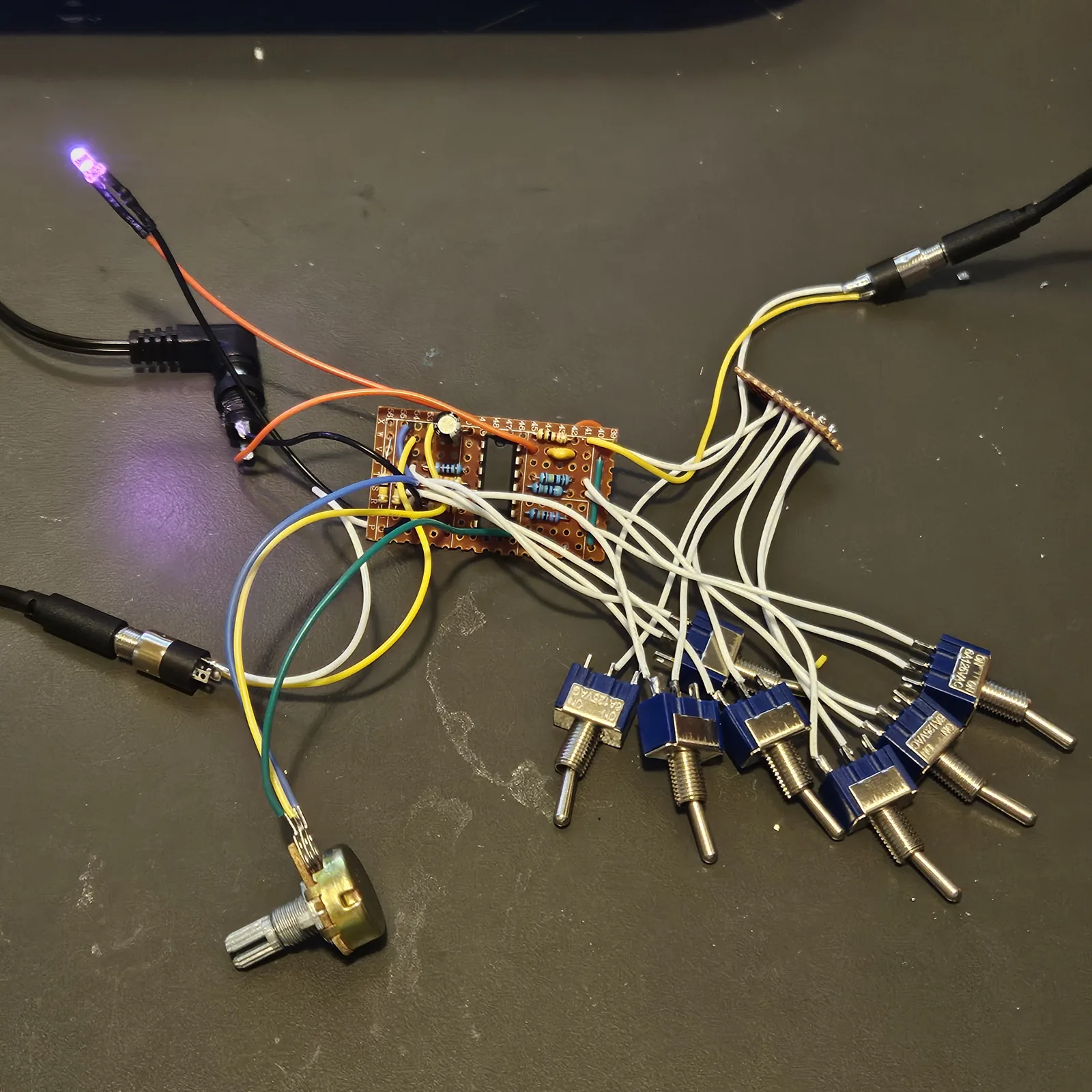
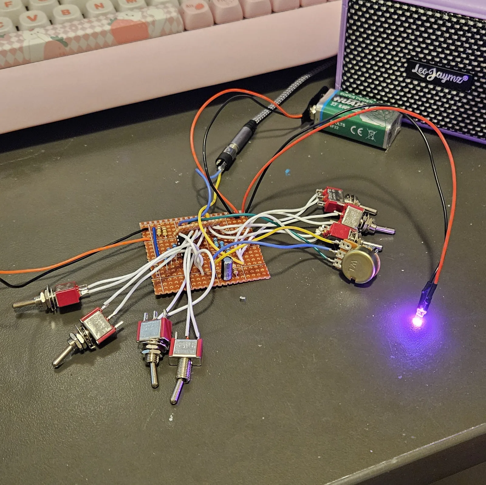
Built on the bench in September 2026, straight off the first drawing of this board - 18 strips by 20 holes, kept here as Grub_Divider_v1.json - and it works. The 9 by 17 file above is the same circuit on less copper, every net checked against the built board, and I have built that one too: it works. In the photo of the first board below, every off-board part is still on flying leads: the seven octave switches, the volume pot, a 9V battery and the cable out to a practice amp. The lit LED is just a power indicator sitting between V+ and GND so you can see it is on - it is not in the layout file, the pad table above does not describe it, and I did not even solder it. I boxed one in a 125B stood on end, drilled from the jacks-on-top template below, and it sold as the Sub Octave Grub.
It wants a strong signal, and a gain stage in front of it is the biggest improvement I have found. I fed the Hive into a dead-bug Hornet I had already built and wired the Hornet's output straight into the input, and it sounds amazing. Grubworks puts a preamp on the board for exactly that, with an Opto Duet and an Atari Punk Console in front of it.
↓ Same box, jacks on top (PDF)
The second sheet keeps every control where this one has it and moves the jacks - power and audio - to the top wall, so the cables leave upward. Two ways to drill one box; pick one.
The seven octave switches run down the right in pitch order, 11 mm apart, with the clock input on the face rather than a wall.
Print at 100% / “Actual size”, never “Fit to page” - check the bar measures exactly 4″ before you touch a drill. The face is 66 by 121 mm but only 42 mm of it is drillable once the lid lip is clear.
The jacks-on-top sheet is the one I drilled, for the Sub Octave Grub; nobody has drilled the face-only one yet. The hole sizes come from the layout file; where they sit is this format applied to it. Offer the sheet up to the box and check it against your own parts before you make a hole.
Circuit after the classic 4024 octave divider, the same idea as the Dead-Bug Grub. Layout drawn by Onion Madder in Copper Bottom.