Locust
A CD4093 swarm and a CD4046 that chases it, on one board · By Onion Madder · Mess O' Pedals
This is two boards that were already on this shelf, put on one piece of copper because they turned out to have the ports for each other. The Cicada NAND is four oscillators on a CD4093, each with an enable pin that stops it dead, and they already sum onto one bus through a resistor each. The Dragonfly VCO is a CD4046, which is not an oscillator chip but a phase-locked loop: give it something to listen to and it hunts, trying to match it. So the swarm becomes the thing the loop listens to, and the loop's own oscillator becomes one of the things that switches a voice on and off. Four voices cannot be matched by one oscillator, so it chases, catches, slips and goes again. That is the sound neither box makes on its own.
What you'll need
tap to expand / collapse
Every value here is taken off the two boards it came from, not chosen again. If you have built the Cicada NAND or the Dragonfly VCO you already own most of this.
- 1× CD4093 quad two-input NAND with Schmitt trigger inputs, 14-pin DIP - spot it: 4093 in the part number (CD4093BE, HEF4093, MC14093), notch marks pin 1. The 4011 is the same pinout with no Schmitt trigger and will not oscillate here, so do not grab one by feel
- 1× CD4046 phase-locked loop, 16-pin DIP - spot it: 4046, and it is the wider chip of the two by two pins. CD4046B and HEF4046B are both fine
- 4× 1K resistor, R1 to R4 - brown black red gold. The floor under each pitch pot, so a voice cannot be turned into a dead short
- 5× 10K, R5 to R8 and R16 - brown black orange gold. Four of them are the voices' share of the mix bus; R16 is the loop filter
- 4× 1M, R9 to R12 - brown black green gold. The pull-up on each enable, which is what makes an open toggle mean the voice runs
- 2× 47K, R13 and R14 - yellow violet orange gold. Two completely different jobs; see the note under the netlist
- 2× 100K, R15 and R17 - brown black yellow gold
- 1× 2K2, R18 - red red red gold, for the panel LED
- 1× 1K, R19 - the resistor between the volume wiper and the output tip
- 1× 1nF ceramic, C3 - marked 102. Voice 3, the shrillest one
- 2× 10nF ceramic, C1 and C10 - marked 103. C1 is voice 1; C10 is the VCO's own timing cap
- 5× 100nF ceramic, C2, C11, C12, C13, C14 - marked 104. C2 is voice 2, the one the VCO gates
- 6× 1µF, C4 to C9 - film for preference. C4 is voice 4's timing cap and the other five are coupling caps
- 1× 10µF electrolytic, C16 - spot it: the stripe is the negative leg, and on this board the positive leg is the one on the mix bus
- 1× 100µF electrolytic, C15 - the bulk cap across the supply, positive to V+
- 1× 1N5817 Schottky, D1 - the band is the cathode, and it points away from the supply pad. Backwards, nothing works; without it, a center-negative plug takes both chips out
- 8× wire links, J1 to J8 - offcut resistor legs are ideal. J7 and J8 are long ones, joining the doubled rails
- Stripboard, 22 strips by 40 holes - about 56 by 102 mm of board
- An IC socket for each chip if you like. The 4046 in particular is worth socketing while nobody has heard this yet
Off the board
- 4× B1M linear potentiometer - the four voice pitch knobs, wired as a variable resistor, wiper plus one outer lug, the third left empty. The 1K floor is on the board
- 1× B100K linear - the VCO pitch knob. This one is a divider, all three lugs used, so it is not wired like the four above. The Dragonfly guide is the one to read if that distinction is new
- 1× B100K linear - the master volume, also a divider
- 3× SPST toggle - the enables for voices 1, 3 and 4
- 1× SPDT ON-OFF-ON toggle - the enable for voice 2. This is the only unusual switch on the box and it is the one that earns its hole
- 1× SPST toggle - MODE, which closes the loop
- 1× SPST toggle - power, in the supply lead
- 1× LED and nothing else; its resistor is on the board
- 1× 3.5 mm jack for the output
- 1× 3.5 mm SWITCHED jack for the input - the switched contact is not optional here, it is the whole input arrangement. See the off-board table
- 1× DC jack, 9 V, and a 9 V supply. A battery works; a wall wart is easier with two chips
- A 1590BB enclosure lying flat, if you box it, plus six knobs
The layout file is the guide
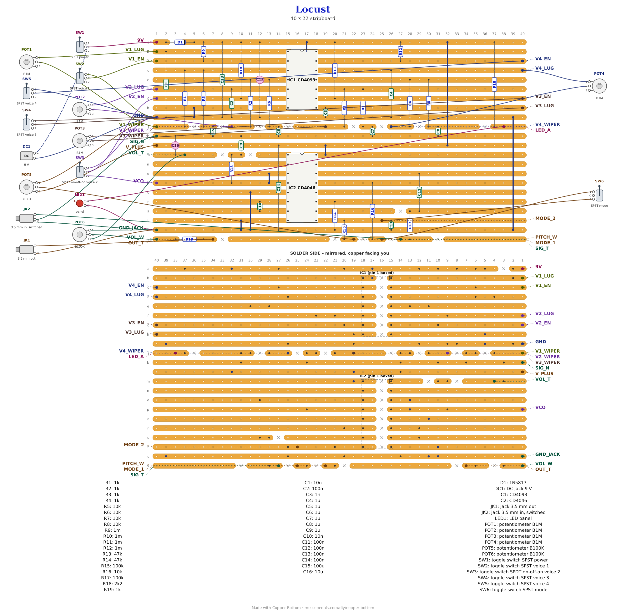
Like every layout on this shelf, the build document for this one is the file itself: ↓ Download Locust.json - import it into Copper Bottom and the editor gives you the board picture, the placement walkthrough, the electrical checks and a printable build sheet, all from the same file. No coordinates are written out on this page on purpose: the editor is the viewer, and a number typed twice is a number that can drift.
Two findings the checker reports are expected. Pins 12 and 15 of the 4046 are orphans - pin 15 is the chip's internal zener and pin 12 is the optional offset resistor, and the Dragonfly VCO leaves both open for the same reason. And R9, R12 and R15 stand on end rather than lying flat: the supply rail and the pins they reach are two strips apart, which is shorter than a quarter-watt body. Standing an axial part up is ordinary; it only changes how tall the finished board is.
The netlist
Quoted verbatim from the layout file. It was written from the board, so checking the board against it can only pass - what it is for is carrying the circuit somewhere else, and telling you what each strip is supposed to be doing while you stare at it.
The two 47K resistors are not a pair. R13 is the bleed: it is how much of the VCO goes onto the bus the loop is listening to, and its value against the voices' 10K is the whole reason this box does not simply lock and go quiet. R14 replaces the Dragonfly's range pot at pin 11 and sets how high the VCO can go. They are the same value by coincidence, and changing one for the other's reasons will not do what you want.
The off-board wiring
Twenty-six pads leave the board. Six pots, six toggles, an LED, three jacks and the supply.
| Pad | Goes to |
|---|---|
| 9V / GND | The supply, 9 V, through the power toggle: DC jack positive to one side of the toggle, the other side to 9V. GND is the supply negative, and also the silent throw of all four enable toggles |
| V1_LUG / V1_WIPER | Voice 1 pitch pot, B1M. One outer lug to V1_LUG, the wiper to V1_WIPER, the third lug empty. A variable resistor with its 1K floor on the board. V2, V3 and V4 are the same on their own pairs of pads |
| V1_EN / V3_EN / V4_EN | The common lug of each enable toggle. The other side goes to GND. Toggle closed pulls the enable low and that voice stops; open, the 1M on the board holds it high and the voice runs |
| V2_EN | The common lug of the ON-OFF-ON toggle, and the one control that makes this board what it is. One throw to GND, the center to nothing, the other throw to the VCO pad. Center runs voice 2, one throw silences it, the other hands its enable to the VCO |
| VCO | The VCO's square, straight off pin 4. The only thing that needs it is voice 2's toggle, but it is a clean rail-to-rail square and it will drive a jack through a 1K if you want a clock out |
| V_PLUS / PITCH_W | The VCO pitch pot, B100K, wired as a divider: one outer lug to V_PLUS, the other outer lug to GND, the wiper to PITCH_W. It is a control voltage, not a timing resistor, so all three lugs are used and there is no series floor |
| MODE_1 / MODE_2 | The MODE toggle, one side each. Closed, the phase comparator reaches the VCO and the loop is closed: it chases. Open, the VCO free-runs and the pitch knob is all that steers it |
| SIG_N / SIG_T | The switched input jack. SIG_N goes to the jack's normal contact and SIG_T to its tip. With nothing plugged in the normal is closed and the loop listens to the board's own mix; a plug lifts the normal and the loop listens to whatever you plugged in instead. The sleeve goes to GND_JACK |
| VOL_T / VOL_W / GND_JACK | The master volume, B100K, a divider. VOL_T to one outer lug, GND_JACK to the other, the wiper to VOL_W. Everything the box makes goes through this one knob |
| OUT_T | The output jack tip, through the 1K on the board. Sleeve to GND_JACK, along with the input jack's sleeve and the LED cathode |
| LED_A | The panel LED's anode, through the 2K2 on the board. Cathode to GND_JACK |
How it works, in one breath
Each of the four voices is one NAND gate with a cap from its input to ground and the pitch pot from its output back to that input, which is the oldest CMOS oscillator there is. The second input of each gate is the enable: hold it low and the output is stuck high and the voice is silent. Their four outputs meet through 10K each on a bus, and the bus is the output of the whole box.
The 4046 is listening to that bus. Its signal input is fed from the bus through the switched jack, its phase comparator is watching its own oscillator, and the MODE toggle is what joins the comparator's output to the oscillator's control voltage. Closed, that is a loop: the oscillator is being steered toward whatever it hears. One voice on its own is something it can lock to. Four voices summed is not, so instead of locking it chases - catching one, sliding off it, catching another.
Then the oscillator goes back onto the same bus through 47K, which is about a fifth of what each voice contributes, so the loop hears roughly five percent of itself mixed into what it is chasing. That is enough to matter and not enough to take over. It also means the enable toggles you already have decide whether the loop can lock at all: silence three voices and it has one clear thing to hunt; run all four and it never settles. No extra control was needed for that, which is why the bleed is a resistor and not a knob.
The last wire is the one that closes the circle. The oscillator's square also reaches voice 2's enable through the three-position toggle, so the thing the loop is chasing can be switched on and off by the loop. Slowly that is rhythmic gating. At audio rate it is the harsh gated sound the Cicada gets from a NAND. With MODE closed and the toggle on VCO at the same time there is no settling point at all, because what it chases changes because it chased it.
Voice 2 is the one that gets gated, and the caps are why. The four timing caps are 10nF, 100nF, 1nF and 1µF, so voice 3 is the shrillest, then voice 1, then voice 2, and voice 4 on 1µF is a clicker rather than a tone. Voice 2 sits in the middle of that spread, which is the one worth chopping. Gating the clicker would mostly be gating silence.
Things to try
- Move the bleed. R13 at 100K makes the loop almost deaf to itself and the chase gets calmer; at 22K it hears itself loudly and will probably latch onto its own tail. This is the one resistor worth a socket
- Gate a different voice. The VCO pad and the enable pads are all brought out, so moving the toggle's third wire from V2_EN to V1_EN or V3_EN is a panel change, not a board change
- The range knob back. R14 replaced the Dragonfly's range pot to save a hole. Lift it and wire a B100K in its place, wiper plus one outer lug, and the VCO gets its top end back as a control
- Center-off instead of center-run. Turn R12's twin on voice 2 - the 1M at R10 - into a pull-down to ground rather than a pull-up, and take that toggle's spare throw to V+. Then the middle position is silence, which is easier to find by feel, at the cost of that one toggle reading the opposite way round from its three neighbours
- Point it at something else. The input jack takes anything: another box, a guitar, a phone. The loop does not care what it is chasing
The DC jack is not on the sheet - it goes on a wall, whichever suits your board. Five rows do not fit inside the lid lip, and a barrel jack is the one part that does not want a knob beside it.
Print at 100% / “Actual size”, never “Fit to page” - check the bar measures exactly 4″ before you touch a drill. The dashed line is the 8 mm keep-out for the lid lip and the corner bosses.
Nobody has drilled this one yet. The hole sizes come from the parts; where they sit is this format applied to them, and the spacing assumes knobs no bigger than 18 mm. Offer the sheet up to your own box and your own parts before you make a hole.
The CMOS Schmitt oscillator and the 4046's own application circuit are as old as the chips and belong to nobody. The four voices are the Cicada NAND and the loop is the Dragonfly VCO, both Onion Madder's and both unchanged here. What is new is the three wires between them and the board they share, drawn in Copper Bottom.