Cicada NAND
Four gated voices on one CD4093, drawn in Copper Bottom · By Onion Madder · Mess O' Pedals
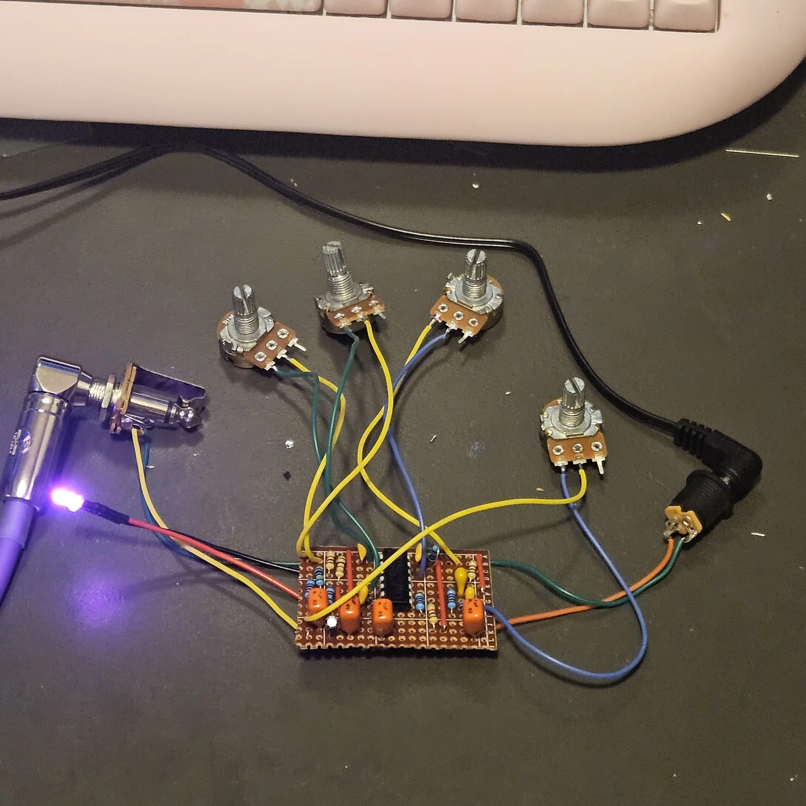
The Dead-Bug Cicada soldered down. A CD4093 holds four Schmitt NAND gates, and a NAND with its two inputs tied into a cap and a resistor is an oscillator - the same trick as the 40106, with one extra wire. That extra wire is the point: a NAND only oscillates while its other input is high, so every voice here has a gate as well as a pitch knob. Pull a gate low and that voice stops dead.
What you'll need
tap to expand / collapse
- 1× CD4093 quad Schmitt NAND, 14-pin DIP - spot it: CD4093 printed on top, notch marks pin 1
- 4× ceramic capacitors, one per voice - the ladder here is 102 (1n), 103 (10n), 104 (100n) and 105 (1 µF). Each one sets that voice's register
- 4× 1K (brown-black-red) - one per pot, in series and not optional: at zero ohms the gate's output ties straight to its own input and the voice dies into a short
- 4× 1M (brown-black-green) - the gate pull-ups. Each one holds a voice enabled until something pulls it down
- 4× 10K (brown-black-orange) and 4× 1 µF non-polarized - the mixer, one pair per voice
- 1× 100n (104) across the supply, and 1× 10 µF electrolytic on the output
- 1× stripboard, 12 strips × 18 holes or larger, and wire for five links
Off the board
- 4× 1M pots, off-board, one per voice - the pitch. Spot it: B1M is the linear one
- 1× 9V supply, or two vape cells in series
- 1× 1/4″ jack for the output - tip to OUT, sleeve to GND_JACK
- Something for each gate, if you want gates. A toggle to ground is an on/off per voice, two bare contacts are a touch plate, a photocell is a light-gated voice. The pads work bare too - every voice runs until you pull its gate low
- An SPST toggle for power, in the positive supply lead between the DC jack or battery and the board's supply pad. Not in the layout file - it is off the board, and every build on this shelf gets one
The layout file is the guide
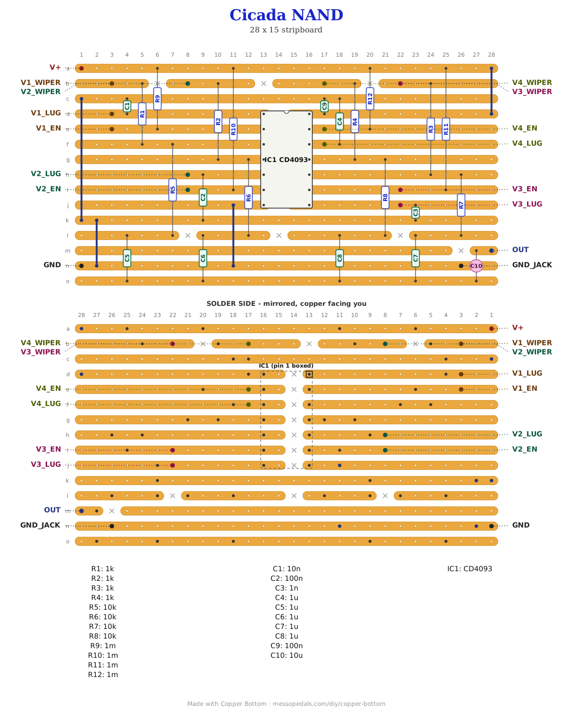
Like the 555 theremin and the Opto Duet, the build document for this one is the file itself: ↓ Download Cicada_NAND.json - import it into Copper Bottom and the editor gives you the board picture, the placement walkthrough, the electrical checks and a printable build sheet, all from the same file. No coordinates are written out on this page on purpose: the editor is the viewer, and a number typed twice is a number that can drift.
The netlist
Quoted verbatim from the layout file. It was written from the board, so checking the board against it can only pass - what it is for is carrying the circuit somewhere else, and telling you what each strip is supposed to be doing while you stare at it.
The off-board wiring
Sixteen pads leave the board.
| Pad | Goes to |
|---|---|
| V+ / GND | The supply. A 4093 is happy anywhere from 3V to 15V, so a 9V battery or a vape pack both work. The 100n sits across the rail on the board |
| V1_LUG … V4_LUG V1_WIPER … V4_WIPER | The four pitch pots, two connections each: wiper to WIPER, either outer lug to LUG, and the third lug left bare. A variable resistor, not a divider - the same wiring as every pitch control on this site |
| V1_EN … V4_EN | The gates, and the reason to build this one rather than a 40106. Each is held high by its own 1M, so the voice runs on its own. Short one to ground and that voice stops. A switch here is an on/off per voice; a pair of contacts is a touch plate; a photocell is a light-gated voice |
| OUT / GND_JACK | Jack tip and sleeve. The 10 µF blocks the DC on the way out |
I have built this four times
The first layout of this board - 15 strips by 28 holes, kept here as Cicada_NAND_v1.json - has gone together four times now and every one of them worked first try. That is the main thing I can tell you about it as a design: it is not fussy, and it does not care much what you hang off it. The 12 by 18 file above is the same circuit on less than half the copper, every net checked against the built board, and it is built too: wired without any of its switches, and it works.
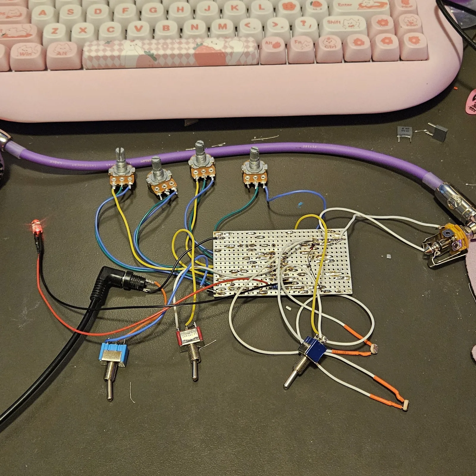
It takes extra bends well, too. Every one I have built picked up a few of my own on top of the drawing and the board never minded. The fourth ended up in a floral tin with five knobs and six toggles on the lid, and it is for sale as Garden Variety.
Those bends are not on the layout and they are not going to be, because they are not the kind of thing you can draw. They interact: what any one of them does depends on where the others are sitting, which is why the tin has no knob list either. Build the board, get it running, and then start bridging things and find your own.
There is a solderless version of this exact circuit. The Cicada NAND on a breadboard is this board unrolled onto a breadboard, net for net - all twenty-four of them match the netlist above. It adds one thing this board does not have, a volume knob, wired as a divider off the board between the output cap and the jack - which is worth doing here too. Nobody has built that one yet, so it wears a draft banner; the copper under it is the built board.
How it works, in one breath
A Schmitt NAND behaves like an inverter with a permission slip. Tie a cap from the input to ground and a resistor from the output back to the input and it chases itself: the cap charges until the input crosses the upper threshold, the output flips, the cap drains until it crosses the lower one, and around it goes. The pot is that resistor, so the knob is the pitch and the cap decides the register.
The second input is the difference. It has to be high for the gate to invert at all, so it is a gate in the musical sense - and because each is held up by nothing but a 1M, almost anything pulling it down will silence that voice. Four outputs then go through their own 10K and 1 µF onto one shared strip, which is the whole mixer: four resistors meeting at a point.
↓ Same box, jacks on top (PDF)
The second sheet keeps every control where this one has it and moves the jacks - power and audio - to the top wall, so the cables leave upward. Two ways to drill one box; pick one.
Four voices, each a pot with its gate switch beside it, so a row across the face is one voice.
Print at 100% / “Actual size”, never “Fit to page” - check the bar measures exactly 4″ before you touch a drill. The face is 66 by 121 mm but only 42 mm of it is drillable once the lid lip is clear.
Nobody has drilled this one yet. The hole sizes come from the layout file; where they sit is this format applied to it. Offer the sheet up to the box and check it against your own parts before you make a hole.
Circuit after the classic 4093 oscillator bank - the same idea as the Dead-Bug Cicada, which is where the name comes from. Layout drawn by Onion Madder in Copper Bottom.