One Shot
Any filthy contact in, one clean pulse out · A TLC555 monostable on nine strips · By Onion Madder · Mess O' Pedals
This is the board I built for The Groaner and then did not need. What it actually is - a 555 monostable with an edge-triggered input - is “any filthy contact in, one clean pulse out”, and that is a permanently useful thing to have on a shelf. It debounces bend points, it turns a footswitch into a fixed-length gate, and it will pulse a motor. Close anything between its two input pads, however briefly and however badly, and the output goes high for about two seconds and then comes back down. Once. However many times the contact bounced.
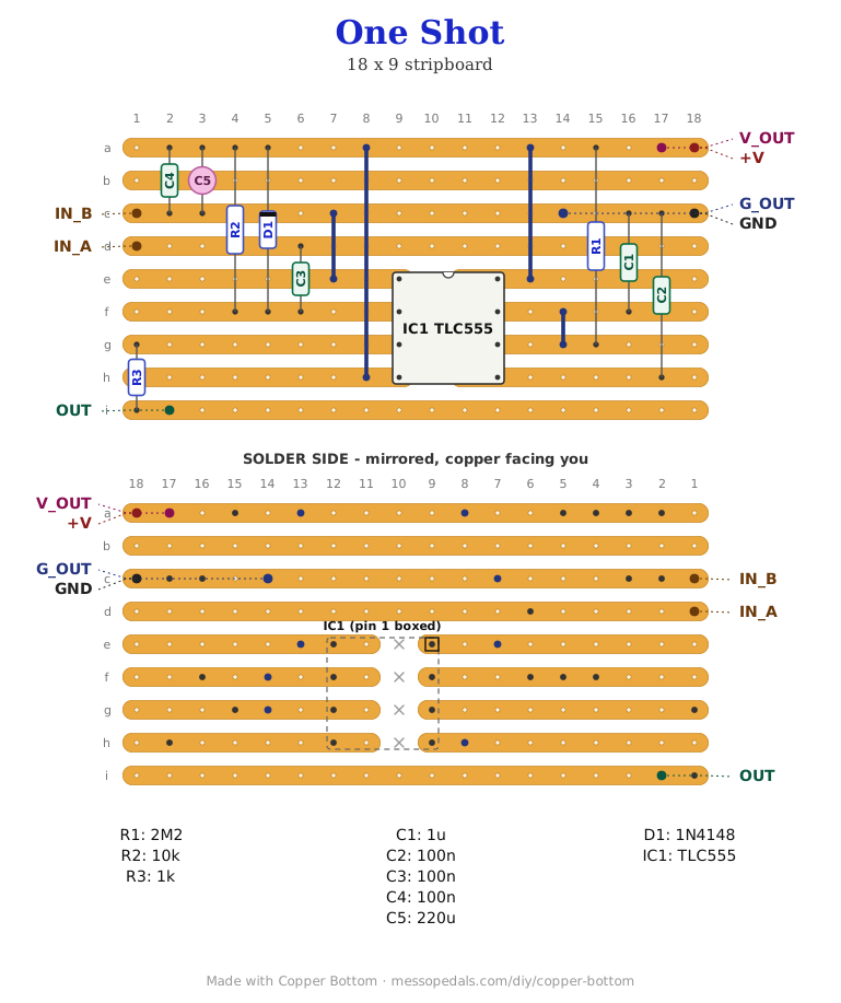
What you'll need
tap to expand / collapse
- 1× TLC555 timer, 8-pin DIP - spot it: TLC555 on top, notch or dot marks pin 1. The CMOS one: it runs from 2V, draws almost nothing idle, and its output swings all the way to the rails. An NE555 works too and wants at least 4.5V
- 1× 1N4148 signal diode (D1) - spot it: tiny glass body, black band at the cathode end. The band goes toward the supply strip
- 1× 2M2 (red-red-green, R1) - the timing resistor. With C1 it sets how long the pulse is
- 1× 10K (brown-black-orange, R2) - holds the trigger pin up
- 1× 1K (brown-black-red, R3) - on the output, so whatever you hang on it cannot hurt the chip. It stands up on this board
- 1× 1 µF (C1) - the timing cap. Film or ceramic; an electrolytic works but its tolerance will move the time
- 3× 100n ceramic (104) - the trigger coupling cap, the control-pin cap, and one across the supply
- 1× 220 µF electrolytic across the supply, for whatever the pulse is driving. Spot it: the stripe marks the negative leg
- 1× stripboard, 9 strips × 18 holes or larger, and wire for four links
Off the board
- A contact. Any two things that touch: a tilt switch, a vibration switch, a footswitch, a bend point, two bits of foil
- Something to pulse. The output is a logic level through 1K; it will drive a CMOS input, an LED straight off it (the 1K on the board is the LED's resistor - it does not need another), or a transistor that drives the real load
- A supply, 3V to 15V - a battery, or the supply of whatever it lives inside. There are pass-through pads so it can feed the load too
The layout file is the guide
Like the 555 theremin and the Opto Duet, the build document for this one is the file itself: ↓ Download One_Shot.json - import it into Copper Bottom and the editor gives you the board picture, the placement walkthrough, the electrical checks and a printable build sheet, all from the same file. No coordinates are written out on this page on purpose: the editor is the viewer, and a number typed twice is a number that can drift.
The checker will report one pin-short on this file, and it is the circuit. Pins 6 and 7 of a 555, threshold and discharge, are tied together in every monostable ever drawn; the editor sees two pins on one strip and says so. Leave them tied.
The netlist
Quoted verbatim from the layout file. It was written from the board, so checking the board against it can only pass - what it is for is carrying the circuit somewhere else, and telling you what each strip is supposed to be doing while you stare at it.
The off-board wiring
Seven pads leave the board, and four of them are the supply going in and coming back out.
| Pad | Goes to |
|---|---|
| +V / GND | Supply in, 3V to 15V |
| V_OUT / G_OUT | The same supply, passed through to whatever you are driving, so the load and the board share one battery and one ground. G_OUT is the return for OUT |
| IN_A / IN_B | The trigger contact, one side each. IN_B sits on the ground rail, so the contact is anything that can pull IN_A to ground for a moment: switch, bend point, footswitch, anything |
| OUT | The pulse. Goes up to the supply voltage for one timed period, then back to 0V, through the 1K on the board. To test it with an LED: long leg (anode) to OUT, short leg (cathode) to G_OUT or GND, no other resistor. It lights for the pulse and goes out |
How it works, in one breath
A 555 in monostable mode sits with its output low and its timing capacitor held empty. The trigger pin is held at the supply by R2, so nothing happens. When the contact closes, IN_A drops to ground and that edge goes through C3 to the trigger pin, which dips below a third of the supply for an instant - long enough. The chip fires: the output goes high, the discharge pin lets go, and C1 starts charging through R1. When C1 reaches two thirds of the supply the chip resets, the output drops, and C1 is emptied again, ready. That takes 1.1 × R1 × C1: 2M2 and 1 µF is about 2.4 seconds.
The point is what happens while it is already running. A second closing of the contact, or a bounce, or a hundred bounces, sends another dip to the trigger pin - and a 555 in this mode ignores triggers until the period is over. So a dirty contact goes in, and one clean pulse of a fixed length comes out. D1 catches the trigger pin when the contact opens and C3 tries to fling it above the supply; without it a CMOS pin gets a spike it does not like.
One thing to watch for on the bench, unmeasured. Nothing on the board holds IN_A at the supply while the contact is open - C3 is the only thing on that pad. That is fine when the contact is something that lets go cleanly and the cap has time to settle through R2. If a second press ever fails to fire, or the first press after a long rest does, a 100K from IN_A to +V is the fix: it gives the cap a level to come back to. Not on the board because it may not be needed. The bench decides.
Things to try
- Change the pulse length. It is R1 times C1 times 1.1. A 220K makes it a quarter of a second; a 10 µF cap makes it twenty-four. Put a 1M pot in series with a 100K in R1's place and it is a knob, from a tenth of a second to over a second
- Use it on a vibration switch. This is what it was drawn for: those chatter like mad, and a chattering switch straight into a recording module restarts the sample a dozen times a knock. Through this board it starts it once
- Turn a footswitch into a gate. A momentary footswitch on the input and a synth's gate input on the output gives a note of fixed length however long you stand on it
- Drive something bigger. OUT through a 2K2 into a 2N3904's base, the load on its collector, a diode across the load if it is a coil. The strum counter is exactly this circuit, with a comparator in front of it and a counter coil after
Circuit from the 555 datasheet's monostable, with the edge-triggered input every debounce circuit uses. The layout is Onion Madder's, drawn in Copper Bottom, first for The Groaner and then for the shelf.