Onion's Theremin
A real theremin, pitch antenna · By Onion Madder · Mess O' Pedals
My other theremins are light theremins: a photocell, a hand casting a shadow. This one is the real kind. You play it without touching it: your hand near the antenna sets the pitch. Two oscillators run far above hearing, a few hundred kilohertz, one of them pulled lower by the few picofarads your hand adds to the antenna, and what you hear is the difference between them. Three chips on a 22 by 24 board, on 12 V.
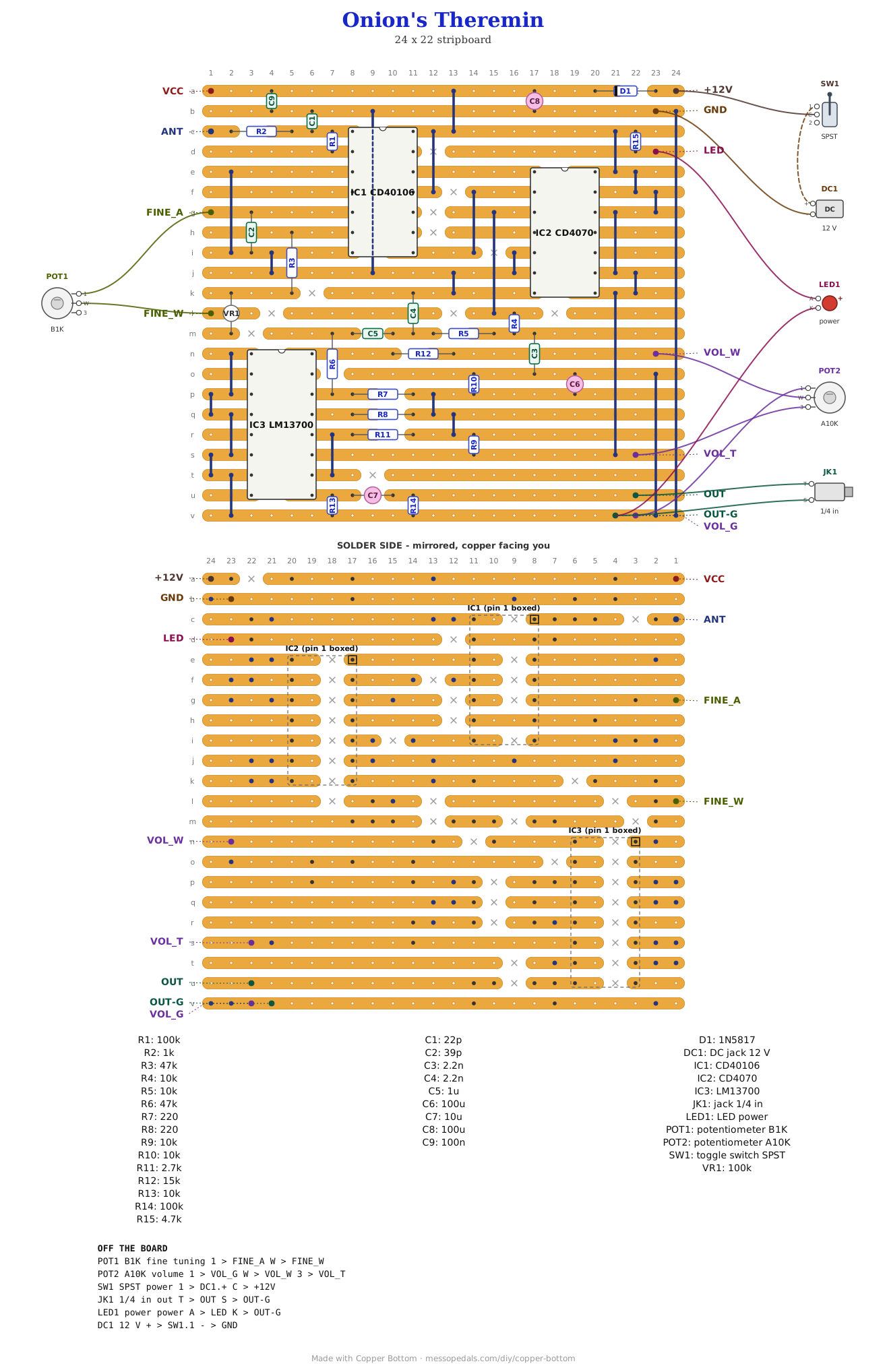
This first board is the pitch side, with a volume knob driving a voltage-controlled amplifier. The amplifier is there so a volume antenna can drive the same point later, the way a full theremin has one antenna for each hand.
What you'll need
tap to expand / collapse
Three chips, fifteen resistors, nine capacitors, a trimmer and a diode on the board, with 25 links, and seven things off it.
- 1× CD40106 hex Schmitt inverter, DIP-14 (IC1) - spot it: fourteen legs, 40106 on top, a notch at the pin 1 end. Both oscillators and their buffers live on this one chip, on purpose, so they drift together. It solders straight to the board
- 1× CD4070 quad XOR, DIP-14 (IC2) - spot it: 4070 on top. A CD4030 has the same pins. One gate is the mixer; the other three have their inputs tied off
- 1× LM13700 dual OTA, DIP-16 (IC3) - spot it: sixteen legs, LM13700 on top. Only amp B, the right-hand row, is used; amp A is switched off by grounding it
- 1× 22 pF ceramic (C1) and 1× 39 pF ceramic (C2) - spot it: small discs marked 22 and 39. Buy C0G (also sold as NP0): they set the two oscillators, and an ordinary ceramic drifts with temperature, which a theremin hears as the pitch wandering
- 2× 2.2 nF (C3, C4) - spot it: marked 222. The two filter caps
- 1× 1 µF film or ceramic (C5) - spot it: marked 105, no stripe, either way around
- 1× 100 nF (C9) - spot it: marked 104. It stands between the two top strips at the left, beside IC1
- 2× 100 µF electrolytic (C6, C8) and 1× 10 µF electrolytic (C7) - spot it: cans with a stripe down one side, the stripe leg negative. C8 stands on strips a and b, stripe down on b. C6 stands on strips o and p, stripe up on o. C7 lies along strip u over a cut, stripe to the right, toward OUT
- 2× 100K (R1, R14) - brown-black-yellow
- 2× 47K (R3, R6) - yellow-violet-orange
- 5× 10K (R4, R5, R9, R10, R13) - brown-black-orange
- 1× 15K (R12) - brown-green-orange
- 1× 4.7K (R15) - yellow-violet-red. It feeds the power LED, which is off the board
- 1× 2.7K (R11) - red-violet-red
- 1× 1K (R2) - brown-black-red. It sits between the antenna and the chip
- 2× 220 ohm (R7, R8) - red-red-brown
- 1× 100K trimmer (VR1, COARSE) - spot it: a small square with a screw slot, marked 104. Its three legs go down column 2 on strips k, l and m; the third leg, on strip m, connects to nothing, because it is used as a variable resistor
- 1× 1N5817 Schottky (D1) - spot it: fat black body, a gray band at one end. Reverse-polarity protection on the supply; it lies along strip a at the top right, band to the left
- 25× wire links - offcuts of component leg. J17 runs under IC1, so it goes in before the chip does
Off the board
- 1× antenna - a metal rod or a telescopic radio antenna, about 30 to 50 cm, on a short wire to ANT. Untested: the length sets how far away your hand starts to play, and that is the first thing to find out
- 1× B1K linear pot - FINE tuning. Lug 1 to FINE_A, wiper to FINE_W, lug 3 empty
- 1× A10K log pot - volume. Lug 3 to VOL_T, wiper to VOL_W, lug 1 to VOL_G
- 1× 1/4 inch jack - the output. Tip to OUT, sleeve to OUT-G
- 1× LED for power - long leg to LED, short leg to OUT-G. R15 on the board sets its current
- 1× DC jack for a 12 V center-negative supply. Not 9 V: the LM13700 wants at least 9.5 V from a single supply
- An SPST toggle for power, in the positive supply lead between the DC jack and the board's +12V pad. Every build on this shelf gets one, and the drawing above shows it
The layout file is the guide
Like every layout on this shelf, the build document for this one is the file itself: ↓ Download Onions_Theremin.json - import it into Copper Bottom and the editor gives you the board picture, the placement walkthrough, the electrical checks and a printable build sheet, all from the same file. No coordinates are written out on this page on purpose: the editor is the viewer, and a number typed twice is a number that can drift.
J17 runs under IC1, down the column between its pin rows, taking ground from strip j up to the rail on strip b. Solder it before the chip. Strips d and h run under IC1 uncut, on purpose: each one carries an oscillator's output across to the gate that buffers it. Every other row under the three chips is cut.
Copper Bottom will say two things, and both are meant. It warns that IC1 has two rows with no cut between its pins, which are strips d and h above. And it reports VR1's third leg as the only thing on its strip, because the trimmer is used as a variable resistor, wiper and one end.
The netlist
My script wrote this from the design and the board was checked against it in Copper Bottom: every connection it names is on the board and nothing on the board is missing from it. PITCH_IN and REF_IN are the two oscillators' timing points, and the script also checks that neither sits beside a strip carrying the other oscillator. MIX is the two mixed together, F1 and F2 the filter, VB half the supply, and IABC the LM13700's control current. The spare outputs and amp A's unused pins are left empty, which is why they are not listed.
The off-board wiring
Eleven pads leave the board, and one more, VCC, is a test point for the meter.
| Pad | Goes to |
|---|---|
| ANT | The antenna, on as short a wire as the box allows. The wire is part of the antenna |
| FINE_A / FINE_W | The FINE pot: lug 1 to FINE_A, the wiper to FINE_W |
| VOL_T / VOL_W / VOL_G | The volume pot: lug 3, the wiper and lug 1 |
| OUT | The output jack tip |
| OUT-G | The output jack sleeve and the LED's short leg. Same net as GND |
| LED | The power LED's long leg |
| +12V / GND | The supply, through the power toggle. DC jack positive to the toggle and the toggle to +12V; negative to GND |
| VCC | Nothing. A place to put the meter: the supply after D1 |
Before you play
Volume down, antenna on, switch it on: the LED should light. Then meter to ground. These numbers are the datasheets and arithmetic, not off a built board.
| Meter | Expect |
|---|---|
| VCC pad, IC1 pin 14, IC3 pin 11 | The supply minus about 0.3 V, the drop across D1: about 11.7 V |
| IC1 pins 2 and 6 | About half the supply. They are square waves at a few hundred kilohertz, and a meter shows their average. Near 0 V or near the supply means that oscillator has stopped: look at R1 and C1 for pin 2, the R3, VR1 and FINE chain and C2 for pin 6 |
| IC3 pins 13 and 14 | About half the supply, near 5.9 V, from R9 and R10 |
| IC3 pin 16 | About 1.2 V with the volume up, near 0 with it down. The volume knob works by moving this |
| IC3 pin 9 | About 1.4 V under pin 12, so around 4.4 V |
Tuning it
A theremin has to be tuned before it plays, and again after it warms up. Plug it into an amp at a low volume, turn the volume knob up, set FINE to the middle, and keep your hands at least an arm's length from the antenna.
- Turn VR1 slowly with a plastic trimmer tool. A metal screwdriver that close to the oscillators moves the pitch on its own. Somewhere in its turn a whistle sweeps down to a low growl, goes silent, and comes back up on the other side
- Stop just to one side of the silence, then bring your hand toward the antenna. The note should rise as your hand comes in. If it falls, you are on the wrong side: go back through the silence and try again
- Now FINE sets where the bottom of the range sits, with your hand away: silence, or a low hum, whichever you like to start from
It wants a ground. The antenna senses your hand against the circuit's ground, and the circuit floats unless something holds it there. Plugged into an amp it is grounded through the jack sleeve, which should be enough. If the range is tiny with nothing plugged in, that is why. All of this is the theory, untested on a bench.
How it works, in one breath
One CD40106 holds both oscillators. Each is a Schmitt inverter with a resistor from its output back to its input and a small capacitor from its input to ground. The pitch oscillator's capacitor is C1, 22 pF, plus the antenna itself through R2. A hand near the antenna adds a fraction of a picofarad, and the oscillator slows down by a few hundred hertz out of about 300,000. The reference oscillator is the same with no antenna, tuned by VR1 and FINE to sit just above the pitch oscillator. Because both run on one chip, they share its switching thresholds, its supply and its temperature, so when one drifts the other drifts with it, and the difference between them, the note, mostly stays put.
Each oscillator is buffered by another gate on the same chip, and one XOR gate in the CD4070 mixes the two squares. Out of an XOR comes a fast pulse train whose average rises and falls at the difference between the two frequencies: a triangle wave at the note you hear. R4 and C3, then R5 and C4, smooth away the radio-frequency part. C5 carries the triangle to R6 and R7, which shrink it to a few hundredths of a volt for the LM13700's input. The volume knob sets the current into pin 16, and the LM13700's gain follows that current, so the knob is a voltage-controlled amplifier. Its output across R11 goes through the chip's own buffer to C7 and OUT. The LM13700 rounds the top of the triangle a little, so the tone comes out soft, closer to a voice than a buzz.
The simulation behind those values, with the chips' datasheet limits: the COARSE trimmer reaches silence at every threshold the 40106 is allowed to have, with any antenna from 5 to 25 pF; FINE moves the note about 12 Hz per degree; a 440 Hz note sinks to about 434 Hz as the supply falls from 12 to 9.5 V; and the output is about 2 V peak to peak. What it cannot model is the two oscillators pulling each other into step when they are very close in frequency, which would show up as a patch of silence at the bottom of the range. The board keeps their timing strips apart for that reason, and only building it will say whether that is enough.
Things to try
None of these have been tried.
- A volume antenna. The amplifier is there for it: a second oscillator pair, mixed, filtered and turned into a voltage, can drive pin 16 the way the volume knob does now. That is the next board
- A different antenna. Longer reaches further and plays a wider range; a loop of stiff wire behaves differently from a rod
- A loop pedal after it. A theremin line layered on itself
The heterodyne idea, two oscillators too high to hear beating into one you can, is Leon Theremin's, from 1920. This circuit, the layout and the words are mine, and so is anything wrong with them.