Optical Theremin
A light-controlled CD40106, on a breadboard · By Onion Madder · Mess O' Pedals
A light-controlled oscillator on one chip. Wave a hand over the photoresistor and the pitch follows your shadow. It comes from a single CD40106 hex inverter on a breadboard, needs no soldering at all, and takes about fifteen minutes start to sound. The chip holds six of these, so when one voice stops being enough the mods at the end add more - and two of them beating against each other is where it gets interesting.
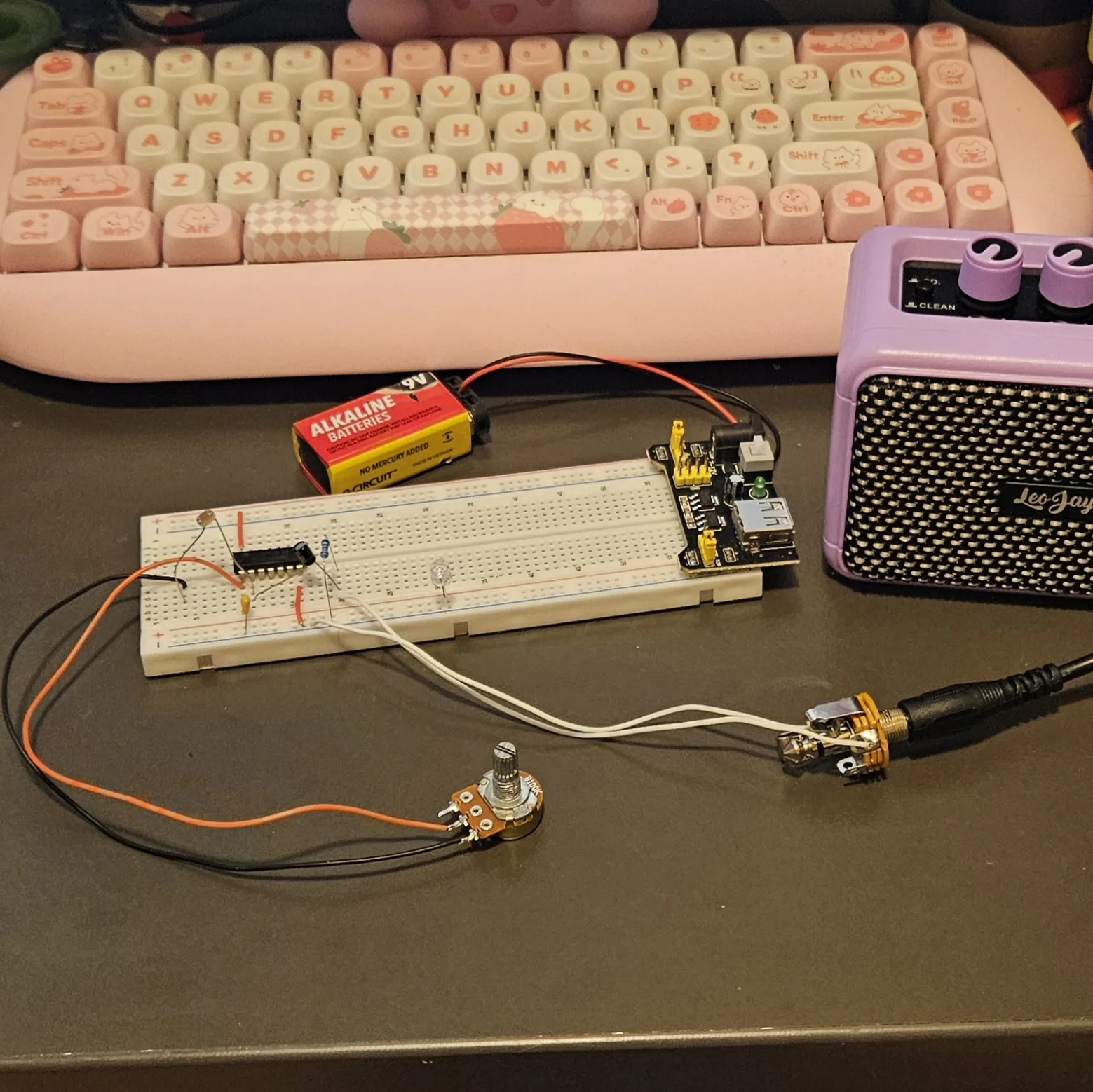
This is the second build in the breadboard series, after the Atari Punk Console. If you've met the Dead-Bug Hive or the MFOS Weird Sound Generator, you already know this chip - they all run on 40106 oscillators. Power is 9–12V DC - a 9V battery, or vape cells in series (three gives 11.1V). Output goes to a small amp or interface.
⚠ Before you start tap to expand / collapse
No iron needed for the basic build - everything pushes into the breadboard. Only the range-pot mod at the end asks for solder.
CMOS has one hard rule: never leave an unused gate input floating. Steps 4–8 ground the five inverters we're not using - skip them and the chip squeals on its own and ignores the photoresistor.
Mind polarity on the 10 µF electrolytic - the stripe marks the minus leg - and on your power leads.
If you power it from a salvaged lithium pack, the usual cell cautions apply - see Do You Want to Survive the Vapocalypse?
What you'll need
tap to expand / collapse
New to the parts? Each line notes how to spot it - the printed marking, the package, or the polarity clue.
- 1× CD40106BE hex Schmitt-trigger inverter, 14-pin DIP - spot it: CD40106 printed on top; a notch marks pin 1
- 1× LDR (GL5528 or similar) - spot it: the little disc with the wavy orange trace across its face. Add one more per extra voice.
- 1× 100K resistor - the range stop (swap for a pot later, see the mods). Spot it: bands brown-black-yellow, or meter it. One more per extra voice.
- 1× 10nF ceramic - the timing cap, and what sets the range. Spot it: printed 103
- For a second voice: 1× 15nF ceramic (22nF also fine) - a different value from voice 1 is the point. Spot it: printed 153 (22nF is 223)
- 1× 10 µF electrolytic - output coupling. Spot it: a little can; the stripe marks the minus leg, longer leg is +. One more per extra voice.
- 2× 10K resistor - one mixing, one bus load. Spot it: bands brown-black-orange. One more mixing resistor per extra voice.
- 7× jumper wire - two for power, five to ground the inputs you are not using
- Breadboard, 9–12V supply, output jack
- For Mod 2 (power LED): 1× LED and 1× 1K resistor - spot it: the LED's long leg is +; the 1K reads brown-black-red
- For Mod 3 (range pots): 1× 100K pot per voice (marked B100K) on flying leads
Reading the breadboard
Letters run along one edge of the board and numbers along the other. A hole is a letter plus a number - E10 is row E, column 10 - and the five holes in a bank that share a number are one electrical point: A10, B10, C10, D10 and E10 are the same node with five ways in. Turn the board so the numbers climb left to right.
Unlike most builds in this series, this one uses both banks: the chip straddles the center channel, its left-side pins landing in row E and its right-side pins in row F, and three unused inputs get grounded to the top rails. So both rail pairs must be powered - if your supply feeds only one pair, bridge + to + and − to − at the free end of the board.
Check your power rails aren't split at the middle of the board. If they are, jumper across the break at both ends.
Quick reference - the whole build on one card
The pinout with its breadboard rows, plus every connection at a glance. The steps below walk through it slowly; this is the bench card.
“A” = input, “Y” = output. Notch marks pin 1, and pin 1 goes in E10 - then every pin lands on the hole shown. Voice 1 is inverter 1, voice 2 is inverter 2; the other four inputs get grounded.
Power (first)
- J10 → top + rail (V+)
- A16 → − rail (GND)
- Idle inputs → − rail: A12 and A14 below, J11, J13 and J15 up top
The voice
- Timing cap: input row → − rail
- 100K: input row → a spare row
- LDR: spare row → output row
- 10µF (+ at output) → 10K → mix bus
The voice, and where a second goes
- V1: in column 10 / out column 11, 10nF, via column 4
- V2: in column 12 / out column 13, 15nF, via column 6
Mix → out
- Column 26 is the mix bus - each voice arrives via its own 10K
- 10K: B26 → − rail (load)
- A26 → jack tip, − rail → jack sleeve
Steps 1–8 The chip and its jumpers
Pin 1 is at the notched end, marked with a dot. Everything in this guide assumes it lands in E10 - put it anywhere else and every hole in this guide shifts. Then all seven jumpers in one pass: two for power, five grounding the inverters you are not using yet.
| Step | Do |
|---|---|
| 1 | Seat the CD40106 across the center channel, notch to the left: pin 1 in E10, pin 7 in E16, pin 8 in F16, pin 14 in F10 |
| 2 | Jumper: J10 to the top + rail |
| 3 | Jumper: A16 to the − rail |
| 4 | Jumper: A12 to the − rail |
| 5 | Jumper: A14 to the − rail |
| 6 | Jumper: J11 to the top − rail |
| 7 | Jumper: J13 to the top − rail |
| 8 | Jumper: J15 to the top − rail |
Steps 2–3 are the chip's power. Steps 4–8 ground the five unused inputs - CMOS inputs must never float, and skipping these is why a 40106 build squeals on its own and ignores the photoresistor. Row 12 left is one of them now; that is where a second voice goes, so its jumper comes out again if you build the mod.
Power up and wave a hand over the photocell. That is the whole build - seventeen steps and no solder. Everything below is optional.
Steps 9–12 The resistors and the photocell
The 100K is the range stop, the photocell is your hand, and the two 10K resistors are the mixing resistor and the bus load. Everything that resists, in one pass.
| Step | Do |
|---|---|
| 9 | Resistor 100K: C10 to C4 |
| 10 | LDR: D4 to D11 |
| 11 | Resistor 10K: C20 to C26 |
| 12 | Resistor 10K: B26 to the − rail |
Steps 13–14 The capacitors
The 10nF is the timing cap and sets the range; the 10 µF carries the voice off to the mix bus and keeps its DC behind.
| Step | Do |
|---|---|
| 13 | Cap 10nF: B10 to the − rail |
| 14 | Cap 10 µF, + leg in B11, other leg in B20 |
Steps 15–17 Out to the jack, and power up
| Step | Do |
|---|---|
| 15 | Wire: A26 to the jack tip |
| 16 | Wire: − rail to the jack sleeve |
| 17 | Power: 9–12V positive to the + rail, negative to the − rail - and both rail pairs fed (bridge + to + and − to − at the free end if your supply lands on one pair) |
Demo What it actually sounds like
Filmed with one voice built, before the second went in. A hand moving over the single photocell - the pitch follows the light, so every shadow you cast is a note. Build the second voice and you get two of these beating against each other.
Filmed by Onion Madder on the actual breadboard, at the one-voice stage. 21 seconds, sound on.
⚠ If it doesn't work
| Symptom | Check |
|---|---|
| No sound at all | Steps 2 and 3. This is the fault nine times out of ten. |
| Constant squeal, ignores the LDRs | Steps 4–7. An unused input is floating. |
| Sound but no pitch change | The 100K and the photocell - the chain isn't reaching back to column 11. |
| Pitch far too high, barely audible | Too much light, or the 100K range stop in step 9 is missing. |
| Pitch too low, clicking | Timing cap too large. Drop the 10nF in step 13 to 4.7nF (printed 472). |
| One voice only | That voice's 10 µF is missing or in backwards, or its 10K into the mix bus is not in. |
| Built Mod 1 and the new voice is silent | Mod 1 step 1 - the grounding jumper from step 4 is still in, holding its input at ground. |
| Built Mod 1 and both voices sound identical | Mod 1 step 2 - wrong value, both timing caps are 10nF. They have to differ. |
Mods
Do these after the basic build works, one at a time, so you always know what changed. The second voice is the one to do first - it is where this circuit stops being a demo and starts being an instrument.
Mod 1 Add a second voice
The same five parts as the first voice, one inverter down, with a 15nF cap instead of 10nF. A different value is the whole point: two voices in different ranges beat against each other, grab, lock and break apart as your hand moves. Two the same just sound like one fat buzz.
| Step | Do |
|---|---|
| 1 | Pull the grounding jumper from step 4 (A12) - column 12 is about to become an input again |
| 2 | Cap 15nF: B12 to the − rail |
| 3 | Resistor 100K: C12 to C6 |
| 4 | LDR 2: D6 to D13 |
| 5 | Cap 10 µF, + leg in B13, other leg in B24 |
| 6 | Resistor 10K: C24 to D26 |
Step 1 is the one people miss. Leave that jumper in and you have shorted your new voice's input to ground, so it sits there silent while everything else works.
Want more? There are six inverters on the chip. Keep going and you are building the Breadboard Hive - the same five parts per voice, six times, with pots in place of photocells.
Mod 2 A power LED
Two parts, no soldering, and worth it the first time you spend ten minutes debugging a build that simply was not powered. It tells you the rails are live and nothing else.
| Step | Do |
|---|---|
| 1 | Resistor 1K: + rail to any free column - say A40 |
| 2 | LED: long leg (+) in B40, short leg to the − rail |
The resistor is not optional - an LED straight across 9V draws whatever it likes and dies. 1K gives a clearly visible glow at 9V; drop to 470 Ω if you want it brighter, or go up to 4.7K if it is dazzling you on a dark bench. The long leg is the anode and goes to +; the flat spot on the rim marks the other side.
It doubles as something to play the theremin with, if you bend it over toward the photocell.
Mod 3 Range pots
The 100K resistor sets how far the pitch can climb. Swapping it for a pot lets you slide the playable window up and down while you play. A panel pot will not sit in a breadboard, so it goes on flying leads - this is the one part of the build that wants a soldering iron.
| Step | Do |
|---|---|
| 1 | Remove the 100K resistor placed in step 9 |
| 2 | Solder a bridge between the pot's middle lug and either outer lug. Use the middle lug and the other outer lug as your two connections |
| 3 | Wire: A10 to the pot's free outer lug |
| 4 | Wire: A4 to the pot's middle lug |
| 5 | If you built Mod 1, repeat for that voice: remove its 100K, then wire A12 and A6 to a second pot the same way |
How it works, in one breath
A Schmitt-trigger inverter with a resistor from its output back to its input and a cap from that input to ground is a relaxation oscillator - the same trick as the Hive. Here the feedback resistor is a photoresistor: more light means less resistance means higher pitch, so your hand is the knob. A fixed 100K in series is the range stop that keeps bright light from running the pitch into ultrasound. Build that twice with two different caps, give the voice its own 10K into a mix bus, and you've got an instrument played with shadows. Build it a second time on the next inverter, with a different cap, and the two voices beat against each other - grabbing, locking and breaking apart as your hand moves. That is the mod at the end.
Things to try
- Swell, don't jump. Cup a hand over the LDR for a slow swell instead of a jump.
- Play it with a flashlight. A phone light gives you far more range than shadow alone, and a much steadier hand.
- Swap the timing cap. 1 µF in place of the 10nF drops the whole thing below hearing, into a slow click you can watch. 1nF sends it up into a whistle.
- With Mod 1 built: chase the lock. Get the two voices to nearly the same pitch. They grab each other, lock, then break apart as you move your hand. That lurch is the best sound the circuit makes.
- With Mod 1 built: cover both at once - the beat rate changes, not just the pitch. And swapping one voice's cap for 1 µF turns it into a slow click that stutters the other.
- Fill the chip. There are six inverters. Keep adding voices on rows 14 left, 11 right, 13 right and 15 right and you arrive at the Breadboard Hive, or its soldered twin the Dead-Bug Hive.
The 40106 oscillator is folk knowledge of the DIY-synth / Lunetta world - the same building block behind Ray Wilson's MFOS Weird Sound Generator and my own Dead-Bug Hive. This breadboard recipe, wiring, and words are my own. Build it, bend it, make it yours.