Opto Wobble
The Opto Duet with an LFO on its pin 5s, and a CV input · By Onion Madder · Mess O' Pedals
The Opto Duet is two 555s coupled by nothing but light: a slow engine ticks, its LED flashes, and the flash bends the voice. This puts my Dual-Wave LFO on the same board and sends its output into pin 5 of either 555, through an on-off-on toggle and a dual 50K pot. Pin 5 is where a 555 keeps its reference voltage, so the LFO wobbles the engine's tempo or the voice's pitch, whichever the toggle picks. A CV jack goes into the engine's pin 5 as well, through 47K. In this box the Duet's two photocell eyes are knobs, tempo and pitch, and the one vactrol inside still carries the engine's flash to the voice.
What you'll need
tap to expand / collapse
Everything from both boards, plus one resistor and the wobble controls. The part numbers below are this board's; the LFO's parts are renumbered from its own page so nothing collides.
- 2× NE555 timer, 8-pin DIP (IC1, IC2) - spot it: NE555 printed on top, notch marks pin 1
- 1× NE5532 dual op-amp, 8-pin DIP (IC3) - the LFO. Spot it: 5532 in the part number, a notch at one end
- 1× 1N5817 Schottky (D1) - spot it: black body, gray band. Reverse-polarity protection, and it protects the LFO too: it runs from the same rail
- 2× 47K (yellow-violet-orange) - R6, the LFO's rate floor, and R10, which carries the CV input onto IC1's pin 5
- 1× 100K (brown-black-yellow) (R9) - the LFO comparator's feedback. It stands on end, across two holes
- 2× 10K (brown-black-orange) (R7, R8) - the LFO's half-rail divider
- 2× 1K (brown-black-red) (R1, R3) - one per 555 timing chain
- 2× 100R (brown-black-brown) (R2, R4) - the output resistors
- 1× 1 µF film (C10) - the LFO's timing cap. Film, not ceramic
- 1× 10 µF electrolytic (C1) - the engine's timing cap
- 1× 47 µF electrolytic (C11) - holds the LFO's half rail still
- 3× 100 µF electrolytic (C3, C6, C7) - two output couplers and one across the rails. Spot it: the stripe marks the negative leg
- 4× 100n ceramic (104) (C4, C8, C9, C12) - the voice's timing cap and a decoupling cap beside each chip
- 2× 10n ceramic (103) (C2, C5) - the pin 5 caps, one per 555. They stay: the LFO and the CV go in beside them
- Stripboard, 18 strips × 23 holes or larger, and wire for seventeen links. J15, J16 and J17 are the ones that join the two halves: J15 the grounds, J16 and J17 the supply, by way of strip j
Off the board
- 1× 2K pot - TEMPO, where the Duet has its tempo eye. Wired as a variable resistor, lug 1 and wiper; lug 3 stays empty
- 1× 100K pot - PITCH, where the Duet has its pitch eye. Lug 1 and wiper; lug 3 stays empty
- 1× photocell and 1× LED, sealed face to face in heat-shrink - the vactrol, inside the box. The LED runs bare, no resistor, the same as on the Opto Duet
- 1× 100K linear pot (B100K) - the LFO rate. Wiper and lug 3; lug 1 stays empty
- 1× 1K linear pot (B1K) - the LFO blend, all three lugs. Its wiper is what feeds the wobble: triangle at one end of the knob, square at the other
- 1× dual 50K pot - WOBBLE, one gang per 555. Each gang is wired as a variable resistor, lug 1 and wiper, with nothing in series: see Built, and heard
- 1× on-off-on toggle - LFO: sends the wobble to the engine, nowhere, or the voice
- 1× 1/4″ jack - the line out, in place of the speaker
- 1× 3.5 mm jack - CV in
- 1× LED and a 4K7 resistor (yellow-violet-red) - the power light, from VCC to ground
- 1× DC jack, 12V, center-negative, and an SPST toggle for power in the positive lead
- An upright 125B - the drill templates are in the rail
The layout file is the guide
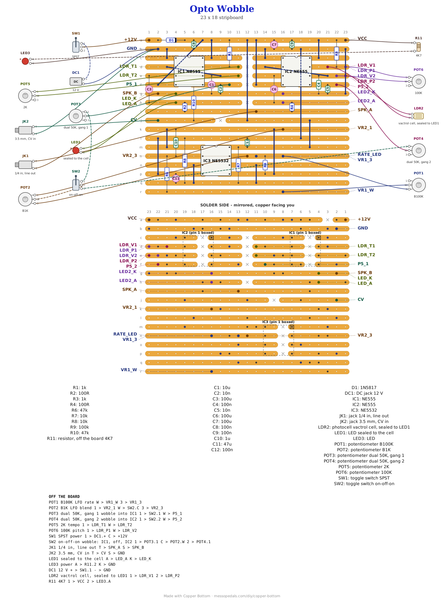
Like every layout on this shelf, the build document for this one is the file itself: ↓ Download Opto_Wobble.json - import it into Copper Bottom and the editor gives you the board picture, the placement walkthrough, the electrical checks and a printable build sheet, all from the same file. No coordinates are written out on this page on purpose: the editor is the viewer, and a number typed twice is a number that can drift.
Two boards, hole for hole. The file was built from the two shipped layout files, not redrawn, and it only exists because every net of both came through intact - the generator refuses to write it otherwise. The editor's four warnings on it are the Opto Duet's own: C1 is a squeeze beside IC1, and R2 and R4 stand on end.
The netlist
Quoted verbatim from the layout file, and emitted from the copper rather than typed
beside it. The lines worth finding are IC1_CTRL and IC2_CTRL, the
two pin 5 strips, and TRIANGLE and SQUARE, the two ends of the blend knob that feeds the wobble.
The off-board wiring
| Pad | Goes to |
|---|---|
| +12V / GND | The supply, 12V center-negative, through the power toggle to +12V. D1 on the board takes it from there, and the LFO runs from the same rail. GND also takes the CV jack's sleeve and the power LED's cathode |
| VCC | The 4K7, then the power LED's anode |
| LDR_T1 / LDR_T2 | TEMPO, the 2K pot, lug 1 and wiper, where the tempo eye would go |
| LDR_P1 / LDR_V2 | PITCH, the 100K pot, lug 1 and wiper, where the pitch eye would go |
| LDR_V1 / LDR_P2 | The vactrol's photocell. LDR_V1 and LDR_P1 are one strip and LDR_V2 and LDR_P2 the other, so it sits in parallel with PITCH |
| LED_A / LED_K | The vactrol's LED, sealed to that photocell |
| SPK_A / SPK_B | The line out: tip to SPK_A, sleeve to SPK_B |
| VR2_1 / VR2_3 | The blend pot, lug 1 and lug 3. Its wiper goes to the common of the on-off-on toggle |
| P5_1 / P5_2 | The wobble. One throw of the toggle goes to lug 1 of the dual pot's first gang, whose wiper lands on P5_1, IC1's pin 5. The other throw goes to the second gang, whose wiper lands on P5_2, IC2's pin 5. Center is off |
| CV | The CV in jack's tip. R10, 47K, is on the board |
| VR1_3 / VR1_W | The rate pot, lug 3 and wiper |
| LED2_A / LED2_K / RATE_LED | Nothing in this box. They are the Opto Duet's indicator and the LFO's rate LED, left on the board for anyone who wants them back |
Built, and heard
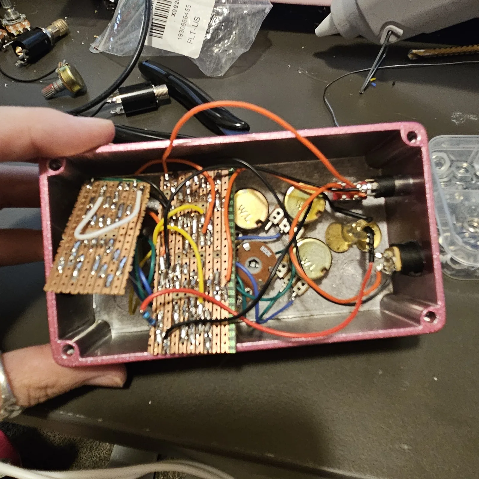
Built on two boards - my Opto Duet v2 and my Dual-Wave LFO - wired the way this page describes, and it sounds great. The dual pot has nothing in series with it on purpose. At the bottom of the knob the LFO drives pin 5 directly and it gets noisy, and I like it noisy, so it stays that way.
How it works, in one breath
A 555 decides when its timing cap is full by comparing it against a reference, and pin 5 is that reference. It normally sits at two thirds of the supply on an internal divider, with a 10n cap to hold it steady. Push pin 5 up and the cap has further to charge, so the chip slows down; pull it down and it speeds up. So the LFO on pin 5 of the engine wobbles the tempo of the flashes, and on pin 5 of the voice it wobbles the pitch. The dual pot is how hard it pushes: turned up it is a gentle sway, and at the bottom there is nothing between the LFO and pin 5, so it overpowers the reference and the chip starts to chatter. That is the noise.
The CV input is the same idea from outside the box. R10, 47K, keeps whatever you plug in from overpowering pin 5, so a CV bends the engine's tempo rather than grabbing it. The LFO itself is the Dual-Wave LFO exactly as its own page describes it, running from the Duet's protected rail.
Things to try
None of these have been tried. They are the obvious knobs.
- A floor under the dual pot. 10K to 22K in series with each gang keeps the wobble clean all the way down, if you want a sway and never the grit.
- The eyes back. Photocells on the LDR_T and LDR_P pads instead of the TEMPO and PITCH pots, the Opto Duet's way, and the room light plays it again.
- CV into the voice. A second 47K from a second jack onto P5_2 does for the pitch what R10 does for the tempo.
- Clock it from the Spider Sequencer into the CV input, and each step moves the engine.
Two of my own layouts on one board: the Opto Duet, whose engine-and-voice arrangement is mine, and the Dual-Wave LFO, whose triangle-and-square pair came from the Experimentalists Anonymous archive. The wobble wiring, the layout and the words are Onion Madder's, drawn in Copper Bottom.