Opto Duet 556
The Opto Duet on one NE556 instead of two 555s, drawn in Copper Bottom and built · By Onion Madder · Mess O' Pedals
The Opto Duet is two 555s: a slow one flashing an LED that is sealed against a photocell, and a fast one whose pitch that photocell sets. An NE556 is two 555s in one 14-pin package, so the same circuit fits on one chip. This page is only what changes. Everything about how it sounds, which cells to grab, why the LED lives behind the cap and how to box it is on the Opto Duet page, and it all still applies.
⚠ Before you start tap to expand / collapse
This board has been built and it works. Meter your strips against the netlist before the chip goes in anyway - it is the cheapest check there is, and a cut in the wrong place looks exactly like a good one.
Four electrolytics, one diode, two LEDs care which way around they go. C1, C3, C6 and C7 have a stripe on the minus leg. D1's band points at the rail, away from the supply pad. Both LEDs: long leg to the A pad.
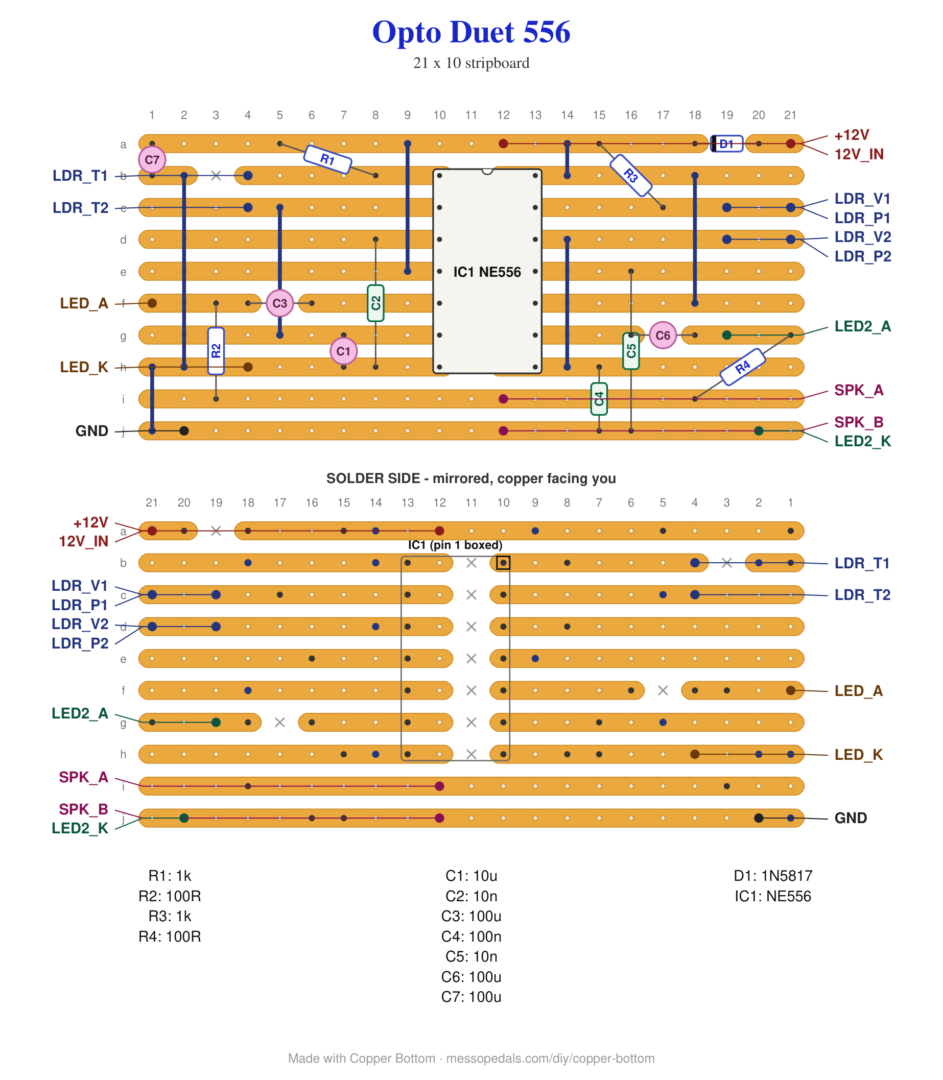
D1 is on the board this time, standing on end at the top right, and it is the only path from the supply pad to the rail. Leave it out and nothing powers up, which is the point: a center-positive plug does nothing instead of killing the chip.
What you'll need
tap to expand / collapse
The Opto Duet's list, with two lines changed:
- 1× NE556 dual timer, 14-pin DIP, instead of two NE555s - spot it: NE556 or NA556 printed on top, notch marks pin 1. A TLC556 is the same pins in CMOS and works down to 2V
- 1× stripboard, 10 strips × 21 holes or larger, instead of 9 by 26 - one strip taller, five holes shorter
- Everything else is the same part in the same job: 2× 1K, 2× 100R, 1× 10µF, 1× 100n, 2× 10n, 3× 100µF, 1× 1N5817, 3× photocell, 2× LED, a speaker, heat-shrink for the vactrol, and a 12V supply or a fresh 9V battery. The Opto Duet page says how to spot each one and why the three cells you grab matter
Off the board
- Everything off the board is the Opto Duet's list, unchanged: three photocells, two LEDs, the speaker, the supply toggle and the DC jack. Same fourteen pads, same names
The layout file is the guide
As with every layout on this shelf, the build document is the file itself: ↓ Download Opto_Duet_556.json - import it into Copper Bottom and the editor gives you the board picture, the placement walkthrough, the electrical checks and a printable build sheet, all from the same file. No coordinates are written out on this page on purpose: the editor is the viewer, and a number typed twice is a number that can drift.
What moved, and what did not
A 556 puts one timer on pins 1 to 6 and the other on pins 8 to 13, with ground on 7 and the supply on 14, so the two halves sit either side of the chip: everything left of IC1 is timer 1, the tempo engine, and everything right of it is timer 2, the voice. Each copper strip through the chip is one pin on each side of the cut. That is the whole translation.
| Job | Opto Duet, two 555s | Here, one 556 |
|---|---|---|
| Tempo: discharge / threshold / control | IC1 pins 7 / 6 / 5 | pins 1 / 2 / 3 |
| Tempo: reset / output / trigger | IC1 pins 4 / 3 / 2 | pins 4 / 5 / 6 |
| Voice: trigger / output / reset | IC2 pins 2 / 3 / 4 | pins 8 / 9 / 10 |
| Voice: control / threshold / discharge | IC2 pins 5 / 6 / 7 | pins 11 / 12 / 13 |
| Ground / supply | pins 1 / 8 on each chip | pin 7 / pin 14, once |
Three things are different on the copper and none of them is the circuit. D1 is on the board, standing on end at the top right, so the supply pad is called 12V_IN and a second pad, +12V, sits on the rail after it: probe that one, and expect about 11.7V from a fresh 12V supply. Each 100µF coupler lies across a cut in its output strip, so the strip is the 555 output on one side of the cap and the LED node on the other. And C7 goes into a short ground stub at the top left rather than reaching for the ground rail. The fourteen pads that leave the board carry the same names as the Opto Duet's and go to the same places - the off-board wiring table there is this board's too, with the one change that the diode is no longer in the wire.
Copper Bottom knows the NE556 as of v1.1.1, so the checks read its pins by name: reset 1, reset 2 and the supply sharing the rail is wiring, not a short, and an unconnected control pin would be caught. Open the file in an older copy and it falls back to a bare 14-pin DIP, which checks less and says so.
The netlist
Quoted verbatim from the layout file. It was written from the board, so checking the board against it can only pass - what it is for is carrying the circuit somewhere else, and telling you what each strip is supposed to be doing while you stare at it. Every net here is one of the Opto Duet's with the pin numbers translated.
Built, and heard
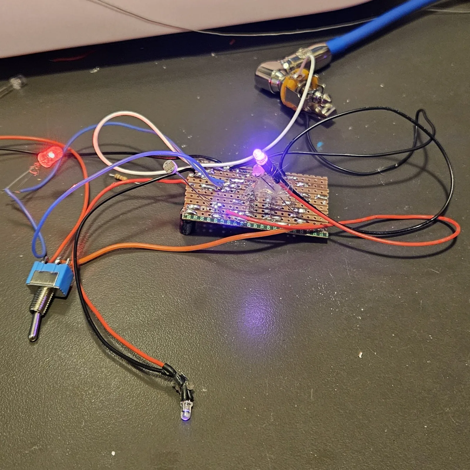
Built on the bench in September 2026, straight off the file above, and confirmed working. So the pin translation below is proven rather than derived: the one-chip board does what the two-chip one does. Not boxed yet; the Opto Duet's drill templates apply as they are, same fourteen pads, same names.
How it works
Exactly as the Opto Duet does, and that page says it properly: the slow timer flashes an LED, the LED is sealed against a photocell, the photocell is the fast timer's timing resistor, and a second cell in parallel with it faces the room so your hand plays it too. Both outputs meet at the speaker through their own 100R. The 556 changes none of it; the two timers inside share nothing but the rails, just as two separate chips would.
The circuit is the Opto Duet, my own. This is the same board redrawn for the one-chip part, in Copper Bottom, with every connection of the two-chip build asserted before the file was written.