Switchboard
Three chips, two knobs, a pattern that wanders on its own · By Onion Madder · Mess O' Pedals
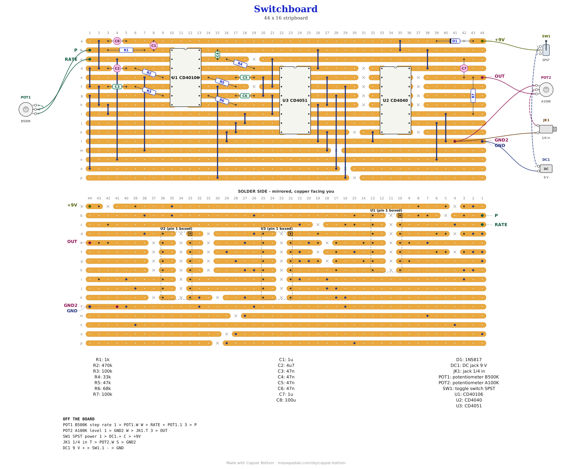
A sequencer with no pots on the steps. Four gates of a 40106 are four fixed tones, set by four resistors. A fifth gate is the clock, on the rate knob, and a CD4040 counts it. Two of the counter's bits drive the address of a CD4051, an eight-way switch, whose inputs are wired tone, rest, tone, rest, so the output steps through a four-beat pattern with silence between the notes. The third address bit comes from a sixth gate running on its own, slowly, on a 470K and 4.7 µF, so every second or so the switchboard changes which pair of tones it is playing. Two knobs, rate and level, and it wanders by itself.
What you'll need
tap to expand / collapse
Sixteen parts on the board plus the links, and five off it. The four tone resistors are the tuning; change them and it is a different tune.
- 1× CD40106 hex Schmitt inverter, DIP-14 (U1) - spot it: fourteen legs, the number printed on top, a notch at one end. All six gates used: four tones, the clock and the drift. Fit a socket
- 1× CD4040 12-stage binary counter, DIP-16 (U2) - spot it: sixteen legs, notch at one end. Counts the clock; only Q2 and Q3 leave it. Fit a socket
- 1× CD4051 8-channel analog mux, DIP-16 (U3) - spot it: sixteen legs, notch at one end. One of eight inputs through to the common pin, chosen by three address bits. Fit a socket
- 1× 1N5817 Schottky (D1) - spot it: fat black body, a gray band at one end. Reverse-polarity protection on the supply
- 1× 470K resistor (R2) - spot it: bands yellow-violet-yellow. The drift oscillator's resistor, with C2. Bigger is slower
- 2× 100K resistor (R3, R7) - spot it: bands brown-black-yellow. R3 tunes voice 1, the lowest; R7 ties the output down for the level pot
- 1× 68K resistor (R6) - spot it: bands blue-gray-orange. Tunes voice 2
- 1× 47K resistor (R5) - spot it: bands yellow-violet-orange. Tunes voice 3
- 1× 33K resistor (R4) - spot it: bands orange-orange-orange. Tunes voice 4, the highest. The four tone resistors are the tuning; with equal caps a smaller resistor is a higher note
- 1× 1K resistor (R1) - spot it: bands brown-black-red. In series with the rate pot, so the clock can never see zero ohms
- 4× 47nF ceramic (C3, C4, C5, C6) - spot it: printed 473. One timing cap per voice. Equal on purpose, so the resistors alone set the intervals. C1 and C4 go to the supply rail rather than ground, which an oscillator does not mind
- 2× 1 µF electrolytic (C1, C7) - spot it: a small can with a stripe down one side; the stripe leg is the negative one. C1 is the clock's timing cap, on the rate pot; C7 couples the output. Stripes: C1 toward pin 1, C7 toward the level pot
- 1× 4.7 µF electrolytic (C2) - spot it: a small can with a stripe down one side; the stripe leg is the negative one. The drift cap, with R2. Stripe to ground
- 1× 100 µF electrolytic (C8) - spot it: a small can with a stripe down one side; the stripe leg is the negative one. The supply reservoir. Stripe to ground
- 25× wire links - offcuts of component leg
- 2× DIP-16 sockets and 1× DIP-14 socket
Off the board
- 1× B500K linear pot - step rate. A variable resistor: lug 3 to P, wiper to RATE, wiper jumpered to lug 1. R1 is its 1K floor
- 1× A100K log pot - level. Lug 3 to OUT, lug 1 to GND2, wiper to the output jack tip
- 1× 1/4 inch jack - out. Tip to the level wiper, sleeve to GND2
- 1× DC jack, 9 V center negative
- An SPST toggle for power, in the positive supply lead between the DC jack and the board's +9V pad. Every build on this shelf gets one, and the drawing above shows it
The layout file is the guide
Like every layout on this shelf, the build document for this one is the file itself: ↓ Download Switchboard.json - import it into Copper Bottom and the editor gives you the board picture, the placement walkthrough, the electrical checks and a printable build sheet, all from the same file. No coordinates are written out on this page on purpose: the editor is the viewer, and a number typed twice is a number that can drift.
Ground is strip l, with GND and GND2 at its right-hand end; the 4051's four grounded inputs and the counter's reset are on the same net. Four of the mux's eight inputs are wired straight to ground - X2, X3, X6 and X7 - and those are the rests. That is the pattern, on the copper, and there is nothing to tune.
The netlist
My script wrote this from the design and the board was checked against it in Copper Bottom: every connection it names is on the board and nothing on the board is missing from it. The lines to read are QA and QB, the two counter bits into the mux's address pins, DRIFT, the slow gate into the third, and V1 to V4, each a tone's output going to one input of the mux. The mux's other four inputs are on GND, which is where the rests come from.
The off-board wiring
Six pads leave the board: the rate pot, the level pot, the jack and the supply. Everything else stays on the copper.
| Pad | Goes to |
|---|---|
| P / RATE | The B500K rate pot. Lug 3 to P, wiper to RATE, wiper jumpered to lug 1. R1 is its 1K floor |
| OUT | Level pot lug 3. The wiper goes to the output jack tip, and lug 1 to GND2 |
| GND2 | Level pot lug 1 and the jack sleeve. Same net as GND |
| +9V / GND | The supply, through the power toggle. DC jack positive to the toggle and the toggle to +9V; negative to GND |
How it works, in one breath
Four gates of the 40106 are four oscillators with a fixed resistor each, 100K, 68K, 47K and 33K, on 47n caps, so four fixed pitches climbing from voice 1 to voice 4, from around two hundred hertz to several hundred. A fifth gate is the clock, on the rate pot and C1, from a couple of ticks a second to audio rate. The 4040 counts the clock. Its Q3 output, which flips every four ticks, drives the mux's A address bit, and Q2, every two, drives B, so the address walks 0, 2, 1, 3 and back, each step two ticks long. The mux's inputs 0 and 1 are voices 1 and 3 and inputs 2 and 3 are ground, so what comes through the common pin is tone, rest, tone, rest: voice 1, nothing, voice 3, nothing.
The sixth gate is the drift: 470K and 4.7 µF, a swing every second or two, on the mux's C bit. When it is high the address is 4 to 7 instead of 0 to 3, and those inputs are voice 4, ground, voice 2, ground. So the same tone-rest-tone-rest pattern runs on the other pair of voices, and the drift swaps pairs whenever it likes, unrelated to the clock. Two pairs, two rates, and a thing that never lines up twice. C7 blocks the DC and the level pot sets how much leaves. That is what the schematic does, and it is a read of the circuit, not of a build.
Things to try
None of these have been tried, because none of this has. They are the obvious knobs.
- Retune it. The four resistors are the four notes. Values in the ratio 4:3:2:1 give octaves and fifths; the ones here were picked to spread, not to tune
- Fill the rests. Lift X2, X3, X6 or X7 off ground and run a wire from another voice, and the pattern is eight notes with no gaps
- Use Q1 and Q2 instead of Q2 and Q3 for the address, and every step is one tick instead of two
- Feed it to the CMOS Ladder Filter, which is what a square-wave sequencer is for
A 4051 stepping through oscillators on a 4040's bits is a Lunetta idiom and belongs to everyone who has ever built one. The drift bit, the tone-rest wiring and the layout are mine, and so is anything wrong with them.