Bridged Amp
Two LM386s pushing one speaker from both ends, for volume · By Onion Madder · Mess O' Pedals
The Hornet is loud. This is the Hornet twice: two LM386s, one fed the signal the right way up and the other upside down, with the speaker between their outputs instead of between one output and ground. Each chip pushes while the other pulls, so the speaker sees twice the swing, which is four times the power off the same 9V battery. That is the datasheet's bridge circuit, and it is the cheapest watt there is. One knob, one LED, a power toggle, 3.5 mm in - an upright box to give the synths a voice that carries.
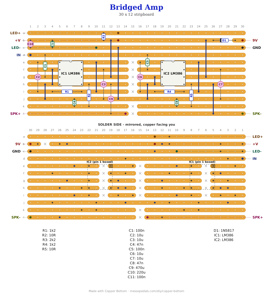
What you'll need
tap to expand / collapse
- 2× LM386 audio amplifier, 8-pin DIP - spot it: LM386 printed on top, notch marks pin 1. N-1 or N-3 for 9V, N-4 if you want to run 12V and above
- 1× 1N5817 Schottky - spot it: black body, silver band. Reverse-polarity protection; a 1N4001 works and costs half a volt
- 2× 1K2 (brown-red-red) - the gain resistors, one per chip
- 2× 10R (brown-black-black) - the Zobel resistors
- 1× 2K2 (red-red-red) for the power LED
- 4× 10 µF electrolytic - two gain caps, two bypass caps. Spot it: the stripe marks the negative leg
- 1× 470 µF electrolytic in series with the speaker, 1× 220 µF electrolytic across the supply
- 2× 100n ceramic (104) - the input coupling caps, one per chip, plus 1× more across the supply
- 2× 47n ceramic (473) - the Zobel caps
- 1× stripboard, 12 strips × 30 holes or larger, and wire for ten links
Off the board
- 1× 10K audio pot (A10K) - the volume, all three lugs
- 1× speaker, 8 Ω, the bigger the better - a 4 Ω will pull more current than a 9V battery enjoys
- 1× LED for the panel, any color - power
- 1× 3.5 mm jack for the input, and an INSULATED 3.5 mm jack or flying leads for the speaker - see the warning under the wiring table
- 1× 9V battery snap or a DC jack, and a toggle for power
- An upright 125B - the drill template further down
The layout file is the guide
Like the 555 theremin and the Opto Duet, the build document for this one is the file itself: ↓ Download Bridged_Amp.json - import it into Copper Bottom and the editor gives you the board picture, the placement walkthrough, the electrical checks and a printable build sheet, all from the same file. No coordinates are written out on this page on purpose: the editor is the viewer, and a number typed twice is a number that can drift.
The netlist
Quoted verbatim from the layout file. It was written from the board, so checking the board against it can only pass - what it is for is carrying the circuit somewhere else, and telling you what each strip is supposed to be doing while you stare at it.
The off-board wiring
Eight pads leave the board.
| Pad | Goes to |
|---|---|
| 9V / GND | The supply, 9V to 12V, through the power toggle. 12V is the LM386's limit unless you have the N-4. GND also takes the input jack sleeve and the volume pot's lug 3 |
| IN | The volume pot's wiper. Lug 1 to the input jack tip, lug 3 to GND - a divider, so it reaches silence |
| LED+ / LED− | The power LED, anode and cathode |
| SPK+ / SPK− | The speaker, one wire to each. SPK+ comes from chip A through the 470 µF; SPK− is chip B's output, straight off the pin |
| +V | Nothing. A test point on the protected rail, and it tells Copper Bottom's checker that strip is a supply |
Neither speaker wire is ground, and that is the one thing this build can get wrong. SPK− is an amplifier output sitting at half the supply. A normal metal 1/4″ or 3.5 mm jack bolts its sleeve to the box, and the box is ground, so a normal jack shorts chip B's output the moment it is tightened - the amp goes quiet, the chip gets hot, and nothing on the board is wrong. Use a plastic-bodied jack, an insulated 3.5 mm jack with a shoulder washer, or wire a speaker inside the box on flying leads. The Hornet did not have this problem because its speaker return was ground.
How it works, in one breath
An LM386 on 9V can swing its output a few volts each way around the middle of the supply, and with the speaker from that output to ground, that swing is what the speaker gets. In a bridge the speaker goes between two outputs. Chip A gets the signal on pin 3, the non-inverting input, and chip B gets the same signal on pin 2, the inverting one, so when A swings up B swings down by the same amount. The speaker sees the difference, twice the swing, and power goes as the square of swing: four times.
Both chips are set to a gain of about 50 - 10 µF and 1K2 between pins 1 and 8 - which bridged is about 100 overall, plenty for a synth at line level. Short the 1K2 and each chip goes to the Hornet's 200, if you want it. Each has the datasheet housekeeping: 10 µF on pin 7 to keep hum out, and a 10R with 47n on the output so it does not oscillate into a long speaker lead. The 470 µF in series with the speaker blocks whatever DC offset the two chips disagree by; with an 8 Ω speaker it rolls off below about 40 Hz, which a small speaker cannot make anyway.
Expect the battery to notice, unmeasured. Four times the power is four times the current on the loud bits, and a 9V battery sags under it - the same sag that took the Opto Duet's LEDs out. If it sounds better on a wall wart than on a battery, that is why, not a fault. On 12V it will be louder again, and that is the LM386's ceiling.
Print at 100% / “Actual size”, never “Fit to page” - check the bar measures exactly 4″ before you touch a drill. The face is 66 by 121 mm but only 42 mm of it is drillable once the lid lip is clear.
Nobody has drilled this one yet. The hole sizes come from the parts; where they sit is this format applied to them. Offer the sheet up to the box and check it against your own parts before you make a hole.
Circuit from the LM386 datasheet's bridge amplifier, with the gain, bypass and Zobel networks from its typical application. The board is the Hornet's block twice; the layout and the box are Onion Madder's, drawn in Copper Bottom.