Hornet on Stripboard
The one-chip speaker amp, soldered down for good.
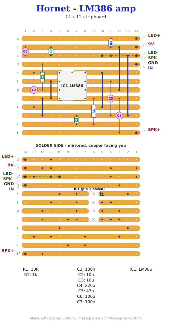
The Dead-Bug Hornet on copper. One LM386, a volume pot and a speaker: the part every other build on this site eventually asks for, because a 555 or a CMOS chip will drive a small speaker badly and an LM386 will drive it properly. Build it once and every noise box you own gets a voice.
What you'll need
tap to expand / collapse
- 1× LM386 audio power amplifier, 8-pin DIP - spot it: LM386 printed on top, with a notch or a dot marking pin 1. The N-1, N-3 and N-4 grades all work here
- 1× 220µF electrolytic (C4) - spot it: the biggest can in the pile. Stripe marks the minus leg, and that leg is the shorter one
- 1× 100µF electrolytic (C6) - spot it: the next size down. Stripe = minus, same as C4
- 2× 10µF electrolytic (C2, C3) - spot it: small cans, both polarised
- 2× 100nF ceramic (C1, C7) - spot it: little disc marked 104. Not fussy which way round
- 1× 47nF ceramic (C5) - spot it: disc marked 473. Half of the Zobel network
- 1× 10R resistor (R1) - spot it: brown – black – black, then gold. The other half of the Zobel
- 1× 1k resistor (R2) - spot it: brown – black – red, then gold. It feeds the power LED and nothing else
- Stripboard, at least 14 columns by 12 strips, plus solid-core wire for the links - spot it: five links on this layout
Off the board
- 1× LED, any color - spot it: the panel indicator. It is optional - leave R2 and the LED out and the amp is unchanged
- 1× volume pot, 10k audio - spot it: wired as a divider, all three lugs used
- 1× 8Ω speaker - spot it: anything small. This is the whole point of the build
- 4V to 12V supply - spot it: a 9V battery is the usual answer. The LM386 will not take more than 12V
- 1× input jack - it feeds the volume pot, and the pot's wiper goes to IN
- 1× DC jack or a 9V battery snap
The layout file is the guide
Every coordinate lives in the layout file rather than being retyped here, which is the point: open it in Copper Bottom and it will walk you through the build hole by hole, check the copper against the netlist, and print a bench sheet. Nothing on this page can drift from it because nothing on this page repeats it.
Twelve strips by fourteen columns. Four cuts, all of them under the chip, and five wire links.
The netlist
Quoted from the layout file exactly as it appears there, because it is the contract: if your board matches this, it is right. Copper Bottom checks it for you.
The off-board wiring
Seven pads leave the board. The volume pot is the only one that needs explaining.
| Pad | Goes to |
|---|---|
| 9V | Supply positive, 4V to 12V |
| GND | Supply negative. The speaker return and the LED cathode share it |
| IN | The volume pot's wiper |
| SPK+ | Speaker, hot leg - it comes off the 220µF output capacitor |
| SPK− | Speaker return. It sits on the ground net |
| LED+ | Panel LED anode, fed through R2 |
| LED− | Panel LED cathode, on the ground net |
The volume pot is a divider, not a variable resistor. All three lugs are used: one outer to the input jack tip, the other outer to GND, and the wiper to IN. Wired that way it reaches silence at one end, which is what a volume control is for. Two lugs would give you a level trim that never quite shuts up.
Print at 100% / “Actual size”, never “Fit to page” - check the bar measures exactly 4″ before you touch a drill. The face is 66 by 121 mm but only 42 mm of it is drillable once the lid lip is clear.
Nobody has drilled this one yet. The hole sizes come from the layout file; where they sit is this format applied to it. Offer the sheet up to the box and check it against your own parts before you make a hole.
How it works, in one breath
The LM386 is a power op-amp with its feedback already inside it. On its own it gives a gain of 20. C2 across pins 1 and 8 takes the internal feedback resistor out of circuit and the gain goes to 200, which is the setting this layout uses and the reason it is loud enough to be worth building.
Everything else is housekeeping. C1 couples the input in and blocks DC from the pot. C3 on pin 7 bypasses the internal bias divider, which quietens the hiss. C4, the big one, couples the output to the speaker and keeps the chip's DC offset out of the coil. R1 and C5 are a Zobel network: a speaker is not a resistor and gets more inductive as the frequency rises, and that pair gives the amplifier something resistive to look at up there so it stays stable instead of oscillating. C6 and C7 hold the supply still, which an amplifier drawing current in bursts very much needs.
R2 and the LED are optional. They are a power indicator hung off the supply and nothing else in the circuit depends on them. Leave both out and the amplifier behaves identically.
LM386 application circuit from the datasheet. Layout drawn in Copper Bottom by Onion Madder.