Robo Rungler
A circuit-bent Rungler talking through a Roboto, in one box · By Onion Madder · Mess O' Pedals
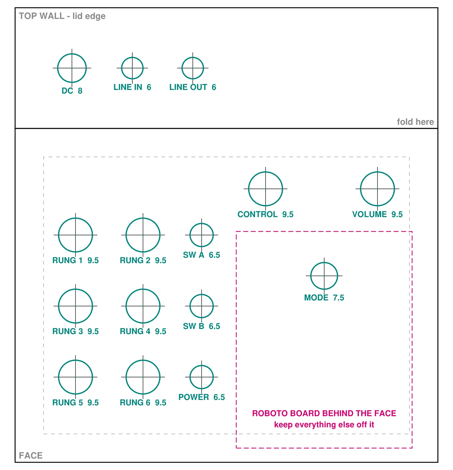
Two things I already have, in one 1590BB. The left half is a circuit-bent version of my stripboard Rungler: six knobs and three switches, one of them power. The right half is a PedalPCB Roboto, their board inspired by the Death By Audio Robot, with its mode rotary and two knobs. The Rungler plays straight into the Roboto, and the Roboto goes to the line out. Plug something into LINE IN and it takes the Rungler's place, so the box is a Roboto for anything else as well. DC, line in and line out sit along the top wall.
What you'll need
tap to expand / collapse
Two boards, each with its own parts list, and a box's worth of panel parts.
- 1× Rungler board - the stripboard Rungler, built from its own guide and its layout file. Its parts list is there
- 1× PedalPCB Roboto (PCB069) - the board from PedalPCB, built from their build document, which carries its parts list. Leave its two pots off the board: they go on the face here and are wired back. Its 2P4T mini rotary is soldered to the board as usual
Off the board
- 6× pots and 2× toggles for the bent Rungler - what each one does and where it lands is not written up yet. See The bends, below
- 1× A100K log pot - the Roboto's VOLUME, wired back to the pads it would have been soldered into
- 1× B500K linear pot - the Roboto's CONTROL, the same way. Both values are PedalPCB's
- 1× switched 3.5 mm jack - LINE IN. It has to be the switched kind, with a third lug the tip rests on when nothing is plugged in. That lug is what lets a cable take the Rungler's place
- 1× 3.5 mm jack - LINE OUT
- 1× DC jack, 9 V center negative
- An SPST toggle for power, one of the three switches on the face, in the positive lead between the DC jack and both boards
- 1× Hammond 1590BB or the same size, 119 by 94 mm on the face
The Roboto board decides the face
The rotary is soldered to the Roboto, so the board hangs off the rotary's pins, flat behind the face, about 12 mm in. The board is 1.95 by 2.4 inches, 49.5 by 61 mm, and the rotary sits on its center line 12.5 mm in from the edge where the pots would go. Nothing with a body can stand over that rectangle, which is the pink box on the template. Everything else is placed around it.
I stood it the way PedalPCB draws it, pot edge toward the jacks. That way CONTROL and VOLUME land almost where their own pads would have put them, above the rotary, and the board's far edge runs down almost to the bottom wall. PedalPCB cut that edge narrower at its corners, which is what keeps it off the corner screw posts. The jacks sit over the Rungler side because the Roboto's knobs fill the top of the right side, and a jack's body behind one of them would hit it. The board can turn to any angle around the rotary if your box wants it another way; redraw the pink box with it.
The Rungler's stripboard, about 33 by 79 mm, lies on the floor of the box under the left half. The Roboto's parts face the lid on the right, so the right half has no floor to spare.
The off-board wiring
Rungler pad names are the ones in the Rungler's layout file; Roboto pad names are the ones printed on PedalPCB's board.
| From | Goes to |
|---|---|
| DC jack positive | The POWER toggle. From the toggle, one wire to the Rungler's +9V pad and one to the Roboto's + pad. Each board has its own reverse-polarity diode |
| DC jack negative | The Rungler's GND, the Roboto's -, and both jack sleeves |
| Rungler level | The level wiper, which used to go to the output jack tip, goes to LINE IN's switched lug, the one the tip rests on with nothing plugged in |
| LINE IN tip | The Roboto's IN. Sleeve to ground. With no plug, the Roboto hears the Rungler; a plug lifts the tip off the switched lug and the cable is all it hears |
| Roboto OUT | LINE OUT tip. Sleeve to ground |
| VOLUME, CONTROL | Each pot's three lugs to the three pads it would have been soldered into, the pot facing the same way, so the knob turns the same direction it would on PedalPCB's layout |
| Roboto SW, A, K | Empty. They are the bypass LED and its footswitch return, and this box has no footswitch: the Roboto is always in the path |
| The bends | Not written up yet. The six Rungler knobs and the two bend switches get a row each here once the box is built |
The bends
Not written up yet. The bends get worked out on the bench with the board running, which is how circuit bending goes, and this section will say what each of the six knobs and the two bend switches does, and where each one lands on the Rungler board, once the box is built. Until then they are numbered on the drill template, RUNG 1 to RUNG 6, SW A and SW B, and the holes are where they are whatever the parts behind them turn out to do.
How it works, in one breath
The Rungler is two oscillators and a shift register that keep bending each other's pitch, so its output is a pattern that never quite repeats; its own guide has the whole of it. Here that output does not go to a jack. It goes into the Roboto's input, through LINE IN's switched lug. The Roboto is built around a Holtek HT8950 voice-changer chip: its input stage brings the signal up, the chip chops it into 8 bits and shifts it, and the rotary picks normal, up, down or arpeggio, with CONTROL nudging the pitch or, in arpeggio, setting the rate. The Roboto was drawn for a guitar, so the Rungler's level knob and the Roboto's own TRIM trimmer are the two places to set how hard it is driven. That is what the two schematics say; nobody has heard them together yet.
The Rungler is Rob Hordijk's, from the Benjolin; the small one on stripboard and the bends are mine. The Roboto is PedalPCB's, inspired by the Death By Audio Robot, and its board and build document are theirs. The box, the wiring between the two and the drill template are mine, and so is anything wrong with them.