Devil's Triangle Drone
Three LM358 oscillators that fight each other · Circuit by Paul Stevenson · Layout and bends by Onion Madder
The original lives here, published October 2012: Devils Triangle Drone Synth on Paul In The Lab. His post is worth reading for why he built it.
Three oscillators, three pitch knobs, three volume knobs, one output. Each one is an LM358 wired as a triangle-and-square oscillator - half the chip compares, half of it integrates, and the two chase each other around forever. A fourth LM358 sums all three. There is no chip in here doing anything clever; it is the same eight-pin op-amp four times over, which is what makes it a good first drone to solder.
That is Paul's circuit, and it is worth building on its own. Mine does not stop there. The board is his exactly as drawn; everything I added is off-board, between the pots, and the best of it is a pair of switches that tie the three oscillators' outputs together so they stop minding their own business and start dragging each other around. That section is below, and it is the reason this one is worth building.
What you'll need
tap to expand / collapse
- 4× LM358 dual op-amp, 8-pin DIP - spot it: LM358 printed on top, and a notch marks pin 1. Three are oscillators, the fourth is the mixer
- 3× 1N4148 diode - spot it: a small glass body with a black band at one end, and that band is the cathode
- 3× 47k (yellow-violet-orange) and 3× 33k (orange-orange-orange) - the comparator's hysteresis pair, one set per oscillator
- 3× 220k (red-red-yellow) - the timing resistor into each integrator
- 5× 10k (brown-black-orange) - two make the half-supply reference, three are the pot tails
- 5× 100k (brown-black-yellow) - three are each channel's output resistor, one is the mixer's feedback, one is channel 3's extra
- 3× 4.7n ceramic (printed 472) - the timing cap, one per oscillator. These are what set the register, and all three are the same - see below
- 1× 1n (102) and 1× 470n (474) ceramic
- 2× 100 µF electrolytic - one across the supply, one coupling the output. Spot it: the stripe marks the minus leg
- 1× stripboard, 22 strips × 20 holes or larger, and hookup wire for nineteen links
Off the board
- 3× 100K pots, off-board, one per oscillator - these are the pitch. Spot it: the taper letter comes before the value, so B100K is the linear one. Paul's layout also has three channel-level pots and you do not want them - see below
- 1× 9V supply - a battery or a wall wart. Mine runs off a wall wart through a toggle switch
- For the bend, which is mine and not Paul's: 2× 1K (brown-black-red) and 2× SPST switches
- 1× DC jack or a 9V battery snap, and 1× toggle in the positive leg so the box has an off
- 1× 1/4″ jack for the output
- Up to 3× SPST switches, one per channel, if you fit them - Paul's advice in place of his own level pots. Optional
- 1× LED, any color, as the indicator - optional, and the pad table says where mine actually lands
The layout file is the guide
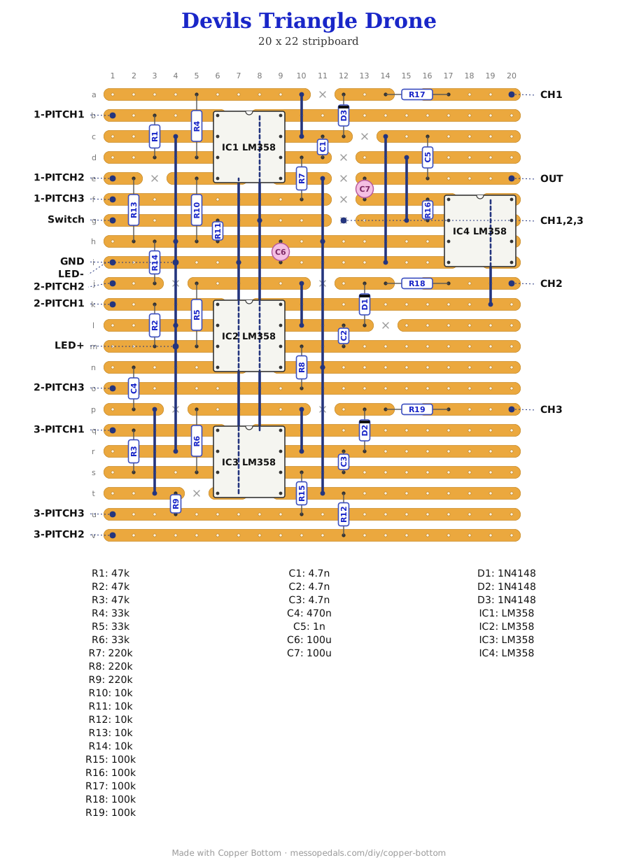
Like the 555 theremin and the Opto Duet, the build document is the file itself: ↓ Download Devils_Triangle_Drone.json - import it into Copper Bottom and the editor gives you the board picture, the placement walkthrough, the electrical checks and a printable build sheet, all from the same file.
This layout is my own drawing of Paul Stevenson's circuit, traced from his stripboard layout and checked against his schematic. The credit and the links are at the bottom of this page - go and read the original.
The netlist
Quoted verbatim from the layout file. It was written from the board, so checking the board against it can only pass - what it is for is carrying the circuit somewhere else, and telling you what each strip is supposed to be doing while you stare at it.
The off-board wiring
Eighteen pads leave the board, nine of them the three pitch pots - plus one wire that is mine and not on the board at all.
| Pad | Goes to |
|---|---|
| Switch / GND | The supply. Mine goes to a toggle switch in the positive leg and then a DC jack; a 9V battery snap works the same. The 100 µF sits across the rail on the board |
| 1-PITCH1 … 3-PITCH3 | The three pitch pots, three lugs each. Lug 1 is that oscillator's square output, lug 2 the wiper, and lug 3 runs to the timing resistor. The pot divides the square drive, which slews the integrator faster or slower without moving the comparator's thresholds - so the level holds steady and only the pitch moves |
| CH1 / CH2 / CH3 | Each channel on its way out, through its own 100k. Paul's layout puts a level pot here and Paul himself says do not bother - his own note is that the channel pots are useless and you should fit on/off switches instead. Mine has no pots here at all: each of these goes to the CH1,2,3 strip, either through a switch or straight |
| CH1,2,3 | Where the three channels meet. One strip into the mixer's inverting input, which is what makes this a summing junction - the three signals add there. If you fit channel switches, this is what they switch on to |
| OUT | Jack tip, through the 100 µF that blocks the DC. My jack sleeve goes back to the GND pad |
| 1-PITCH1 + 2-PITCH1 + 3-PITCH1 my build only | The bend. Pot 3 lug 1 is the hub: a 1K to a switch to pot 1 lug 1, and another 1K to a second switch to pot 2 lug 1. Not in Paul's circuit, and the board does not know about it - it is all between pot lugs. See the bend below |
| LED+ / LED- | A bare indicator LED. On my build LED+ lands on channel 2's comparator node rather than the supply, so it is lit through that oscillator's own 47k and 33k - which is why it is gentle rather than glaring, and why it flickers as you sweep the knobs. It reads about 3V across it. An accident that turned into an activity light |
Nothing in this circuit goes to ground except the chips, the caps and the jack sleeve. Everything in the signal path floats at half the supply, about 4.5V, and the schematic draws that half-supply reference with a symbol that looks very like a ground symbol but is not one. I learned this the hard way: I added three on/off switches and wired them to a common ground strip, and the whole box went silent. Taking the switches back off made it work first time. If you want channel switches, put them in series in the wire from a channel out to the mixer strip, breaking the connection rather than grounding it.
How it works, in one breath
Each oscillator uses both halves of one LM358. The first half is a comparator with its minus input parked on the half-supply reference and its plus input driven by two resistors - a 47k back from its own output and a 33k in from the other half. That pair sets two thresholds, one going up and one coming down. The second half is an integrator: a 4.7n cap across it, a 220k feeding it. The comparator's square output ramps the integrator, the integrator's triangle drags the comparator's plus input across a threshold, it flips, and around it goes.
The pitch pot sits between them, dividing how hard the square drives the ramp. Each oscillator's triangle then goes through a diode and a 100k, and all three meet at the fourth chip's inverting input. Three resistors meeting at a virtual earth is the entire mixer - the 100k across that chip sets the gain, the 100 µF blocks the DC on the way out.
There is a touch bend on this one too, and I found it by accident. Put a finger on lug 1 of pitch pot 3 - the lug carrying channel 3's square output - and it growls and farts like an Atari Punk Console. Let go and it goes back to behaving.
Why it works, as best I can reason it: that lug carries the square wave that drives channel 3's ramp, and a fingertip couples your whole body onto it along with everything your body is picking up out of the air. Mains hum rides in and wobbles how fast the integrator ramps, which drags the pitch around several dozen times a second. Channel 3 is also the one carrying an extra 470n and 220k the other two do not have, so it responds slowly and slurs instead of just buzzing. That is a read of the circuit rather than something I have measured.
Worth doing on purpose: a bare pad, a screw head or a drawing pin wired to that lug, so it is a control rather than an accident. I have not fitted one yet.
Leave the channel pots off
Paul's layout gives each channel a level pot on its way to the mixer, and Paul's own advice is not to fit them: he says the channel pots are useless and to put on/off switches there instead. He is right. Each channel already has a fixed 100k on the way out and they arrive at the mixer at sensible levels; a pot there mostly gives you three ways to make it quieter.
So mine has none. The board runs perfectly happily with a switch in each channel's place, or with nothing there at all and the three wired straight to the mixer strip. That is three fewer pots to mount, three fewer holes to drill, and it is the reason this thing fits a 125B at all.
If you do fit switches, put them in series - CH1 to one side, the CH1,2,3 strip to the other - so the switch simply breaks that channel's wire. Do not ground anything. See the note under the wiring table for what happens if you do.
The bend: make them fight
Built to Paul's drawing, this is three drones in a box that happen to share an output. They do not know about each other. Join their outputs and they do.
Lug 1 of each pitch pot is that oscillator's square output, straight off the op-amp pin. Pot 3 is the hub. Its lug 1 carries the one wire to the board and then two more: a 1K resistor to a switch to pot 1's lug 1, and a second 1K to a second switch to pot 2's lug 1. Two switches, four states - all three apart, 3 with 1, 3 with 2, or everything joined.
Closed, one oscillator's square is pushing on another's through a kilohm, and they start locking, slipping and beating against each other. The knobs stop setting three pitches and start setting who wins.
The 1K is the whole difference, and I tried it both ways. Wired straight, the outputs simply fight: one overpowers the other and it is coarse. Through a kilohm they only lean, so both oscillators keep some of their own character and the result blends instead of clashing - much more musical, and the pitch knobs still do something. It also quietly settles the safety question, because with 1K in the way the current between two disagreeing outputs is only a few milliamps rather than whatever the chips feel like passing.
Channel 3 ends up the anchor, which falls out of the wiring rather than being designed. Pots 1 and 2 each reach pot 3 through one resistor, but they only reach each other through both in series - so they are tied twice as loosely to each other as they are to channel 3. Whatever pot 3 is doing, the other two are drawn to it first.
Everything about this is off the board. Three wires between pot lugs and a switch. The stripboard does not change, so you can build Paul's layout exactly as drawn and decide about this afterwards - which is what I did.
It also turns the one weakness into the whole point. All three timing caps are 4.7n, so unbent this thing is three voices crowded into one register - half a Hive Drone with less range, where the Hive steps six caps a decade apart. I was going to spread those caps out. Do not: oscillators only grab each other like this when they are already close in frequency. Being stuck in one register is exactly why they lock. Spread the caps and you would buy range and lose the bend.
If you do try it without the resistors, know what you are doing: two op-amp outputs wired together means one is pushing current straight into the other, and the only thing stopping it is the chip's own short-circuit limit. An LM358 takes that and survives - people have been bending them this way forever - but it runs warm, and there is no reason to when a 1K sounds better anyway. Go straight to the resistors. Larger values are worth a try too; the further up you go the more each oscillator keeps to itself.
Also a mod: the touch bend
Boxing it up
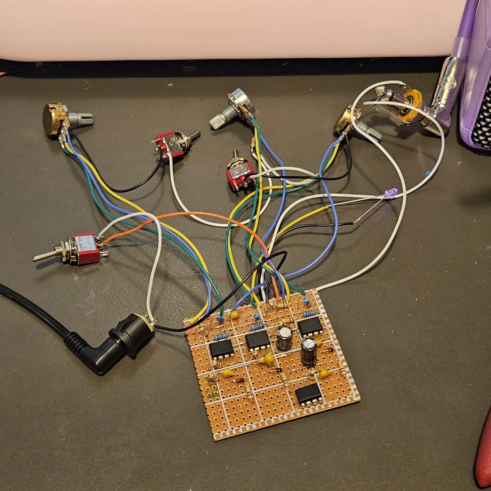
It is in the box. A 125B stood upright - 66 mm across and 121 mm tall - with everything on the face: the three pitch pots down the left, the two bend switches and the power toggle down the right, the indicator LED above them, and the DC jack and output across the bottom. Nine holes. This is the payoff for leaving the channel pots off; twelve would not have fitted.
Nothing goes on the walls, and that is the whole point. This box is meant to stand shoulder to shoulder with others - a row of boxes I can rearrange and swap the way you would rearrange a rack, one circuit per enclosure, patched together into whatever synth I want that day. A jack on a wall is a rule about where that box is allowed to sit. Put every hole on the face and there is no such rule: any box can go anywhere, either way around, touching on both sides.
Stood up, a 125B turns out to be a decent module. 66 mm wide and 121 tall - six of them in a row is under 400 mm, and the height lands within about 7 mm of a Eurorack 3U module, which is a coincidence but a convenient one. The 42 mm of usable face is not this build's problem then, it is the format's spec, and every box after this one gets the same. Worth settling a house layout early: I/O along the bottom, power left, audio right, controls above. Then any box you pick up, you already know where to plug in.
The layout is the circuit. Pot 3 is the hub of the bend, so it sits in the middle of the pot column, and each bend switch is level with the gap between the two pots it joins - the upper switch across from pitch 1 and pitch 3, the lower one across from pitch 3 and pitch 2. You can read what the switches do off the front panel without labelling anything.
Four sizes, none of them fussy: 9.5 mm (3/8″) for the three pot bushings and the output jack, 6.5 mm (1/4″) for the three toggles, 8 mm (5/16″) for the DC jack, and 5 mm for the LED. The LED goes at the top of the switch column, which is where a pedal's indicator lives anyway and happens to be the one place left with room for it.
Standing it up makes the face narrow, and that is the constraint everything else bends around. 66 mm less 12 mm of lid lip and corner boss at each side leaves 42 mm to drill in - about three fingers. That is why the pots take one column and everything else takes the other, and it is why this wants small knobs; a fat 20 mm knob will crowd the switches beside it. The height is the easy direction here, so spread things down the box rather than across it.
Watch the depth on a face-mounted output jack. A 1/4″ jack reaches about 25 mm into a box whose inside is only a little over 30 mm deep, so it will fight the board if they share a corner. Mount the board over to one side and give the jack its own end. Moving the jacks to a wall would be the ordinary fix and this format does not allow it - that is the price of boxes that butt together, and it is worth paying.
↓ Same box, jacks on top (PDF)
The second sheet keeps every control where this one has it and moves the jacks - power and audio - to the top wall, so the cables leave upward. Two ways to drill one box; pick one.
Print at 100% / “Actual size”, never “Fit to page” - check the bar measures exactly 4″ before you touch a drill. The sheet is portrait, which follows from the box: stood upright a 125B unfolds to 145 by 200 mm, taller than it is wide.
Circuit and original stripboard layout by Paul Stevenson, October 2012, published at Paul in the Lab as FroGZLand Audio. This page is my own redraw of his layout in Copper Bottom, with my build of it - the circuit is his. He is also the reason Copper Bottom exists at all.