Atari Punk Console
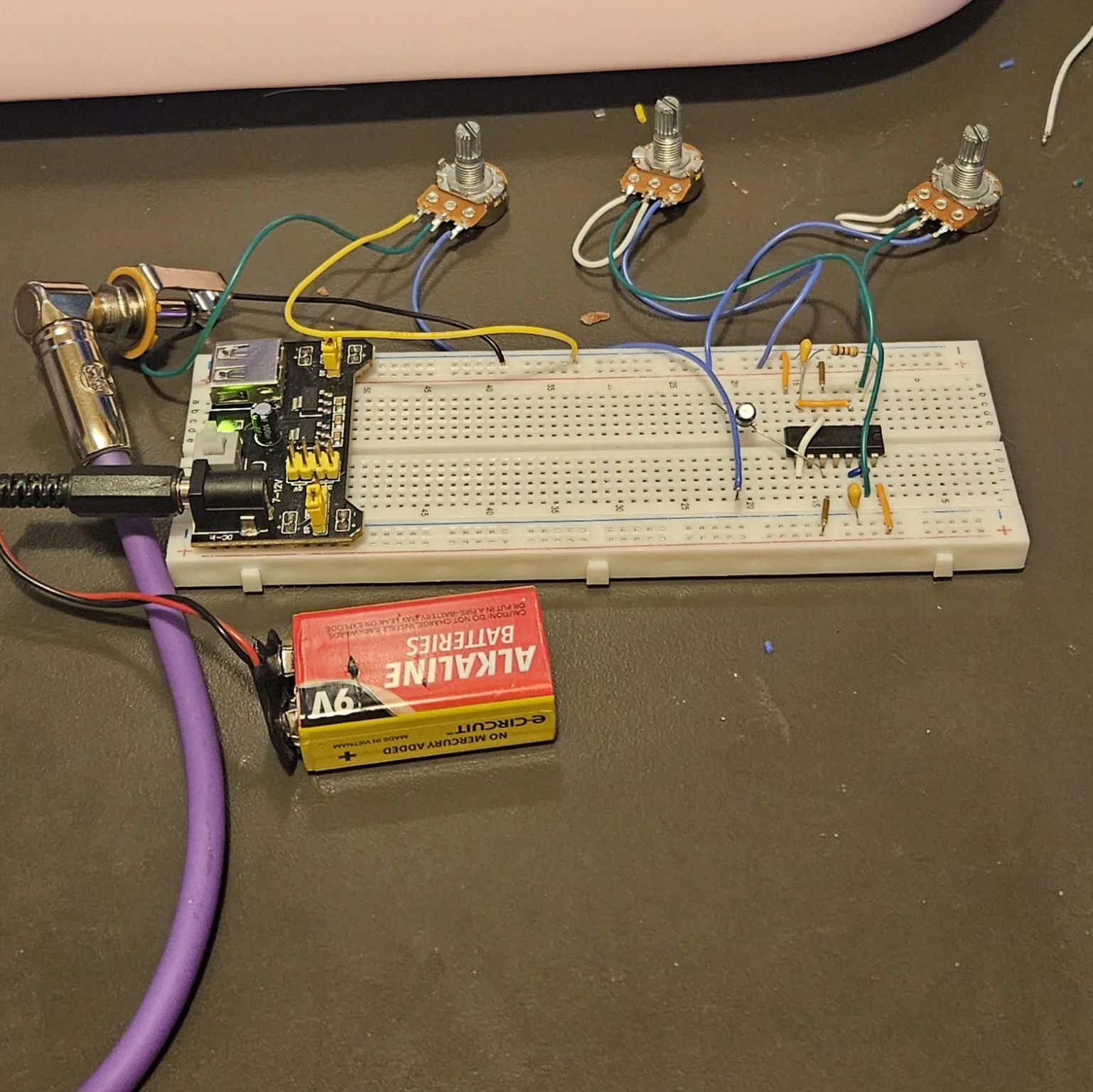
The NE556 stepped tone generator, on a breadboard · By Onion Madder · Mess O' Pedals
Forrest Mims' stepped tone generator - two timers on one chip, where one oscillator fires the other, and when the two rates cross, the pitch jumps in hard steps instead of sliding. That lurch is the whole instrument, and it's why the internet calls this circuit the Atari Punk Console. This one goes together on a breadboard - push parts into holes, follow the rows, and you're making noise in about twenty minutes.
This is the first build in the breadboard series - the same circuit family as the Dead-Bug Mosquito, which is this exact generator soldered point-to-point. Build it here first, get to know it, then graduate to the dead-bug version when you want it permanent. Power is 9V DC - a 9V battery, or vape cells in series. Output goes to a small amp or interface.
⚠ Before you start tap to expand / collapse
Almost no soldering - the breadboard does the holding. The one exception: each of the three pots gets a small solder bridge on its lugs before it's wired in (the steps say exactly where). Three joints total, then the iron goes away.
Mind polarity on the 10 µF electrolytic - the stripe marks the minus leg - and on your power leads. Backwards electrolytics bulge or pop.
If the chip ever gets hot, power off immediately. That means the + rail is shorted to the − rail somewhere. Nothing in this build should even get warm.
If you power it from a salvaged lithium pack, the usual cell cautions apply - see Do You Want to Survive the Vapocalypse?
What you'll need
tap to expand / collapse
New to the parts? Each line notes how to spot it - the printed marking, the package, or the polarity clue.
- 1× NE556 dual timer, 14-pin DIP - spot it: NE556 printed on top; a notch marks pin 1
- 1× 1M pot - knob one, how often the pulses come. Spot it: marked B1M (B = linear taper)
- 1× 500K pot - knob two, how long each pulse lasts. Spot it: marked B500K (or B504)
- 1× 100K pot - volume. Spot it: marked B100K
- 1× 1K resistor - spot it: bands brown-black-red, or meter it
- 2× 10nF ceramic - one timing cap per timer. Spot it: printed 103
- 1× 10 µF electrolytic - output coupling. Spot it: a little can; the stripe marks the minus leg, longer leg is +
- 7× jumper wire
- Breadboard, 9V supply, output jack
- For the optional light mod: 1× LDR (photoresistor, GL5528 or similar - the little disc with the wavy trace) and 1× more 1K resistor
Reading the breadboard
Letters run along one edge of the board and numbers along the other. A hole is a letter plus a number - E10 is row E, column 10 - and the five holes in a bank that share a number are one electrical point: A10, B10, C10, D10 and E10 are the same node with five ways in. Turn the board so the numbers climb left to right.
This build uses both banks: the chip straddles the center channel, its left-side pins landing in row E and its right-side pins in row F. So both rail pairs must be powered - if your supply feeds only one pair, bridge + to + and − to − at the free end of the board.
Check your power rails aren't split at the middle of the board. If they are, jumper across the break at both ends.
The three pots won't sit in a breadboard, so they connect on flying leads. Each one gets prepared before it's wired in - the steps say how.
Quick reference - the whole build on one card
The pinout with its breadboard rows, plus every connection at a glance. The steps below walk through it slowly; this is the bench card.
Timer A on the left, timer B on the right. Notch marks pin 1, and pin 1 goes in E10 - then every pin lands on the hole shown. No mirroring, no mental flipping.
Power (first)
- Row 10 right → + rail (V+)
- Row 16 left → − rail (GND)
- Row 13 left → + rail (reset A high)
- Row 14 right → + rail (reset B high)
Timer A - the oscillator
- 1M pot: + rail → A10
- 1K: B10 → B15
- Tie: C11 ↔ C15
- 10nF: D15 → − rail
Timer B - the one-shot
- Handoff: D14 → G16
- 500K pot: + rail → J11
- Tie: H12 ↔ H11
- 10nF: G12 → − rail
Mix → out
- 10µF: + leg G15 → B22
- Row 22 → volume pot → jack tip
- − rail → jack sleeve
- Volume all the way down before power-up
Steps 1–8 The chip and its jumpers
Pin 1 goes in E10 - put the chip anywhere else and every row below shifts with it. Then all seven jumpers in one pass: two for power, two holding the reset pins high, and three that wire the two halves of the 556 to each other.
| Step | Do |
|---|---|
| 1 | Seat the NE556 across the center channel, notch to the left: pin 1 in E10, pin 7 in E16, pin 8 in F16, pin 14 in F10 |
| 2 | Jumper: J10 to the top + rail |
| 3 | Jumper: A16 to the − rail |
| 4 | Jumper: A13 to the + rail |
| 5 | Jumper: J14 to the top + rail |
| 6 | Jumper: C11 to C15 |
| 7 | Jumper: H12 to H11 |
| 8 | Jumper: D14 to G16 |
Steps 2–3 are the chip's power. Steps 4–5 hold both reset pins high - leave these out and the chip stays switched off. It's the most common miss in the whole build.
Steps 9–12 The resistor and the capacitors
One resistor, two timing caps and the output electrolytic. The two 10nF caps are what set the range the knobs sweep through, so they are the pair to change later.
| Step | Do |
|---|---|
| 9 | Resistor 1K: B10 to B15 |
| 10 | Cap 10nF: D15 to the − rail |
| 11 | Cap 10nF: G12 to the top − rail |
| 12 | Cap 10 µF, + leg in G15, other leg in B22 |
Steps 13–23 Off the board: three pots and the jack
Nothing else goes into the breadboard. Two of the pots are wired as variable resistors, with the middle lug bridged to an outer one; the volume pot is the odd one out and uses all three lugs, which is what lets it reach silence.
| Step | Do |
|---|---|
| 13 | Take the 1M pot. Bridge its middle lug to either outer lug |
| 14 | Wire: the 1M pot's unbridged outer lug to the + rail |
| 15 | Wire: the 1M pot's middle lug to A10 |
| 16 | Take the 500K pot. Bridge its middle lug to either outer lug, same as before |
| 17 | Wire: the 500K pot's unbridged outer lug to the + rail |
| 18 | Wire: the 500K pot's middle lug to J11 |
| 19 | Take the 100K volume pot. Do not bridge this one |
| 20 | Wire: A22 to either outer lug of the volume pot |
| 21 | Wire: the volume pot's other outer lug to the − rail |
| 22 | Wire: the volume pot's middle lug to the jack tip |
| 23 | Wire: − rail to the jack sleeve |
Step 24 Power up
Turn the volume pot all the way down first, then power up: 9V positive to the + rail, negative to the − rail, with both rail pairs fed - bridge + to + and − to − at the free end if your supply lands on one pair. Bring the volume up, sweep the knobs, and start hunting for the steps.
The build in the photo at the top runs at 5V, not 9V. That is a 9V battery going into a power module set to its 5V output, with the module feeding the rails rather than the battery feeding them directly. An NE556 runs from about 4.5V up, so 5V is inside spec and it works. The difference is level rather than pitch: the timing comes from the resistors and the capacitor rather than from the supply, while the chip's output swing follows the supply, so a 5V build plays the same and comes out quieter. 9V is still what the parts list says.
⚠ If it doesn't work
| Symptom | Check |
|---|---|
| No sound at all | Steps 2–5. A floating reset pin holds the whole chip off, and it's the most common miss. |
| A steady tone that won't step | Step 8. Without it the two halves aren't talking. |
| Knob one does nothing | Steps 13–15, and check the bridge is actually on the middle lug. |
| Knob two does nothing | Steps 16–18. |
| Very faint output | Steps 19–22, or the electrolytic in step 12 is in backwards. |
| Slow clicking, no pitch | Both knobs at maximum resistance. Turn them down. |
| Hot chip, nothing works | Power off immediately. Something has the + rail shorted to the − rail. |
Optional Put it under light control
Swapping knob one for a photoresistor turns it into a light-played instrument - wave a hand over it and the steps chase your shadow. Do this after the basic build works, so you know any new weirdness came from the mod.
| Step | Do |
|---|---|
| 24 | Remove the two wires to the 1M pot (steps 14 and 15) |
| 25 | LDR: + rail to D4 |
| 26 | Resistor 1K: C4 to C10 |
The 1K stops the pitch running away into ultrasound under bright light. Knob two still works as normal - keep it. Want two whole voices under light control? That's the Optical Theremin, the next build in this series.
How it works, in one breath
The NE556 is two 555 timers in one 14-pin chip. Timer A free-runs as an oscillator, spitting out a stream of trigger pulses - knob one sets how often they come. Every pulse fires timer B as a one-shot, which holds its output high for a set stretch - knob two sets how long. While a pulse is still running, new triggers get ignored - so as you sweep the knobs, the output snaps between whole ratios of the two rates instead of gliding. Stepped tones, from two knobs and a handful of parts.
Things to try
- Find the steps. Sweep knob two slowly with knob one parked. The pitch climbs, then lurches down an interval, then climbs again. Those jumps are what the circuit is named for - they happen when a new trigger arrives before the previous pulse has finished.
- Live on the edge. Park both knobs somewhere unstable and tap the breadboard. The steps flip either way.
- Bend it. E12 (low side) and F13 (up top) are the two control-voltage pins. A finger across either one bends the pitch; a wire from an LFO or another oscillator does it properly.
- Slow it down. Larger timing caps in steps 10 and 11 drop the whole thing into machine-gun and drone territory. Try 100nF (printed 104).
- Make it permanent. When the breadboard version has earned a box, the Dead-Bug Mosquito is this same circuit soldered point-to-point, with CV inputs and a clock output.
The stepped tone generator is Forrest Mims' circuit, from his Radio Shack notebooks - passed around for decades since as the Atari Punk Console. This breadboard recipe, wiring, and words are my own. Build it, bend it, make it yours.