Opto Duet Grub
A light-coupled beat into seven octaves of divider, on one board · By Onion Madder · Mess O' Pedals
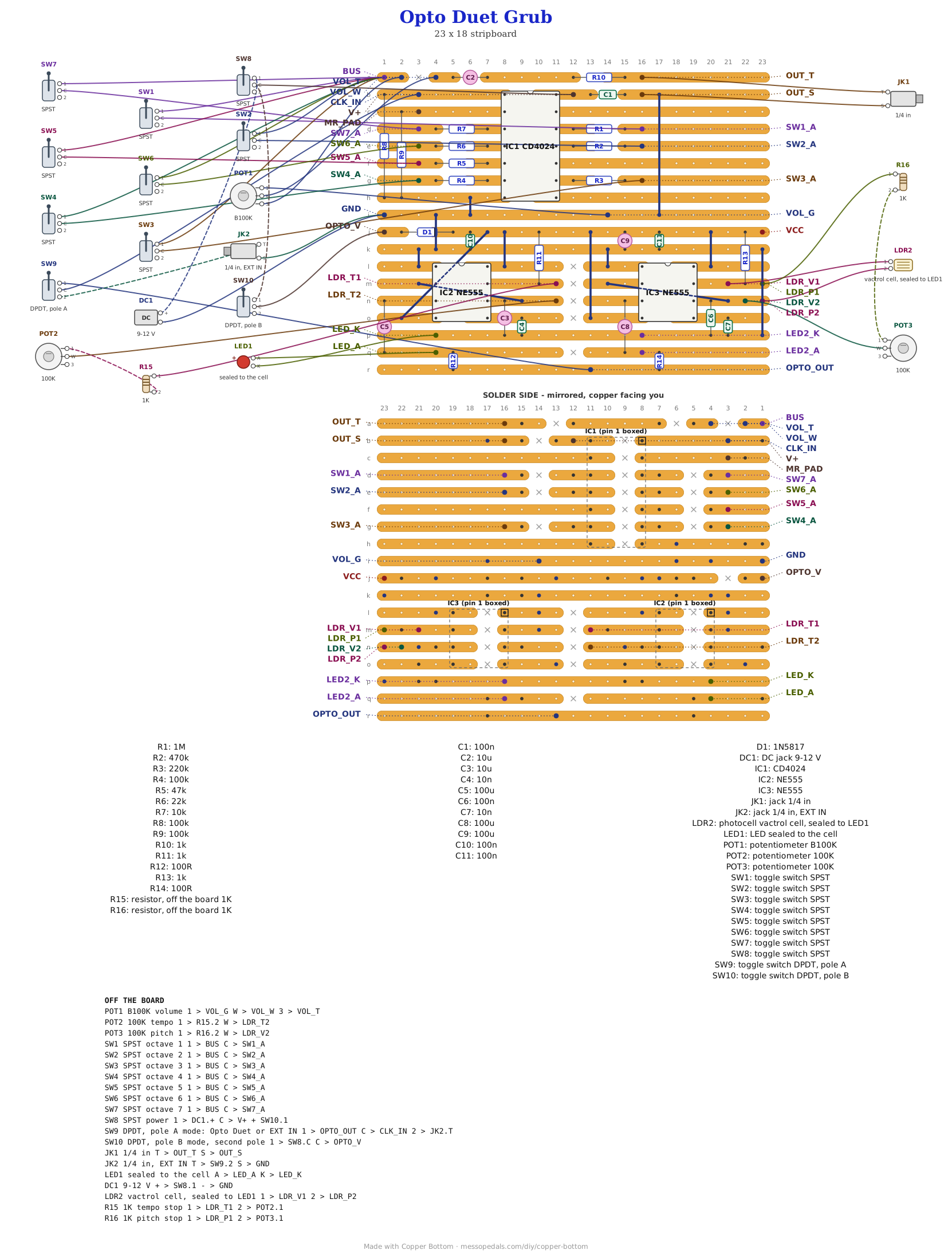
The Opto Duet into the Grub Divider makes its own beat. The Opto Duet is two 555s talking by light: a slow one with a tempo, flashing an LED into a photocell on a fast one, so the fast one chirps on the beat. A CD4024 divides that into seven octaves down, and seven switches pick which octaves sit in the mix. It is rhythmic all by itself, with nothing else plugged in. A MODE toggle hands the divider to an EXT IN jack instead and switches the Opto Duet off, so the Grub still works on anything else you feed it.
What you'll need
tap to expand / collapse
Thirty-eight parts on the board, counting twelve wire links. The Grub half is exactly the Grub Divider's parts with the same reference numbers; the Opto Duet half is exactly the Opto Duet's, renumbered so nothing clashes (its IC1 is IC2 here, its R1 is R11, its C1 is C3, its J1 is J3, and so on up).
- 1× CD4024 seven-stage binary counter, 14-pin DIP (IC1) - spot it: CD4024 printed on top, notch marks pin 1
- 2× NE555 timer, 8-pin DIP (IC2, IC3) - spot it: NE555 printed on top, notch marks pin 1. IC2 is the engine, the slow one with the tempo; IC3 is the voice. Sockets are worth it
- The weighted ladder, one resistor per octave and every value different (R1 to R7): 1M, 470K, 220K, 100K, 47K, 22K, 10K. They are what make this a mixer instead of a selector - get one wrong and that octave is too loud or inaudible
- 2× 100K resistor (R8, R9) - spot it: bands brown-black-yellow. The clock and reset pull-downs. R8 is what the Opto Duet lands on
- 3× 1K resistor (R10, R11, R13) - spot it: bands brown-black-red. R10 is the Grub's output; R11 and R13 are the Opto Duet's, one per timing chain
- 2× 100R resistor (R12, R14) - spot it: bands brown-black-brown. The Opto Duet's two outputs, where they mix. Both stand on end
- 1× 1N5817 Schottky (D1) - spot it: black body, gray band. Band toward the chips. It protects the Opto Duet half only, as on the Opto Duet
- 2× 10nF ceramic (C4, C7) - spot it: printed 103. Pin 5 decoupling, one per 555
- 4× 100nF ceramic (C1, C6, C10, C11) - spot it: printed 104. C6 is the voice's timing cap; the other three sit across the supply, one by each chip
- 2× 10 µF electrolytic (C2, C3) - spot it: a small can, stripe on the minus leg. C3 is the engine's timing cap, the part that turns a scream into a tick; C2 blocks the DC on the Grub's way out
- 3× 100 µF electrolytic (C5, C8, C9) - the Opto Duet's two output caps and one across its rails. Stripe to ground
- 12× wire links (J1 to J12) - offcuts of component leg. Three of the Opto Duet's run diagonally over a 555, two across IC2 and one across IC3, so they go in before the chips or their sockets. J12 is the only one that is new: it joins the two grounds
- 1× stripboard, 18 strips × 23 holes or larger - a cheap board is fine, but turn your iron down
Off the board
- 2× 100K pot - TEMPO and PITCH, in place of the Opto Duet's two eyes. Each one wired as a variable resistor: one outer lug and the wiper, the third lug left empty
- 2× 1K resistor - spot it: brown-black-red. One in series with each of those pots, between the pad and the outer lug, so a knob turned to the end never shorts a 555's pin 7 onto its timing cap. The eyes never needed one, because a photocell never reaches zero
- 1× LED, any color, and 1× photocell (LDR) - the vactrol, sealed face to face in heat-shrink. The LED runs bare, no resistor, as on the Opto Duet
- 1× B100K linear pot - VOLUME, all three lugs
- 1× DPDT toggle, on-on - MODE. One pole picks what the divider hears, the other runs or stops the Opto Duet
- 7× SPST switches, one per octave
- 2× 1/4″ jack - EXT IN and the output
- 1× DC jack and a 9 to 12 V supply. The Opto Duet wants 6 V and up, or its LED stops flashing
- 1× momentary switch between MR_PAD and V+ for a retrigger - optional, the same as on the Grub
- An SPST toggle for power, in the positive supply lead between the DC jack and the board's V+ pad. Not in the layout file - it is off the board, and every build on this shelf gets one
The layout file is the guide
Like every layout on this shelf, the build document for this one is the file itself: ↓ Download Opto_Duet_Grub.json - import it into Copper Bottom and the editor gives you the board picture, the placement walkthrough, the electrical checks and a printable build sheet, all from the same file. No coordinates are written out on this page on purpose: the editor is the viewer, and a number typed twice is a number that can drift.
Two boards in one. Strips a to i are the Grub Divider as I built it, and strips j to r are the Opto Duet as I built it, neither one moved by a hole. J12 is the only copper joining them, for ground. The supplies stay separate on the board: the Grub runs from V+, and the Opto Duet from OPTO_V through its own D1, which is what lets the mode toggle switch it off. Copper Bottom's four warnings on this file are the Opto Duet's own, carried over: C3 standing close by IC2, and R12 and R14 standing on end.
The netlist
Quoted verbatim from the layout file, and emitted from the copper rather than typed
beside it - so checking the board against it can only pass. What it is for is carrying the
circuit somewhere else, and telling you what each strip is doing while you stare at it.
Everything from OPTO_V down is the Opto Duet; the eye pads keep their Opto Duet
names, LDR_T for the tempo and LDR_P and LDR_V for the
voice.
The off-board wiring
Twenty-seven pads take a wire: three knobs, the vactrol, the mode toggle, seven octave switches, two jacks and the supply, with MR_PAD only if you want the retrigger. VCC is a test pad that tells the checker that strip is a supply, and LED2_A and LED2_K can stay empty.
| Pad | Goes to |
|---|---|
| V+ / GND | The supply, through the power toggle. DC jack positive to the toggle and the toggle's common to V+; negative to GND, which is also both jack sleeves |
| OPTO_V | MODE, the second pole. Its common goes to OPTO_V, the Opto Duet's supply ahead of D1. The throw on the same side as OPTO_OUT goes to the power toggle's common, beside the V+ wire; the other throw stays empty. So when the divider is listening to the Opto Duet it runs, and when it is listening to EXT IN it is off and makes nothing |
| OPTO_OUT / CLK_IN | MODE, the first pole. Common to CLK_IN. One throw to OPTO_OUT, where the Opto Duet's two 555s mix; the other to the EXT IN jack's tip. With nothing plugged into EXT IN the divider's input still sits on R8 to ground, so it never floats |
| LDR_T1 / LDR_T2 | TEMPO, a 100K pot, where the tempo eye was: LDR_T1 to a 1K, the 1K to one outer lug, the wiper to LDR_T2, the third lug empty |
| LDR_P1 / LDR_V2 | PITCH, a 100K pot, where the pitch eye was, the same way around: LDR_P1 to a 1K, the 1K to one outer lug, the wiper to LDR_V2 |
| LED_A / LED_K LDR_V1 / LDR_P2 | The vactrol. The LED on LED_A and LED_K, bare, and the photocell on LDR_V1 and LDR_P2, sealed face to face in heat-shrink. LDR_V1 shares a strip with LDR_P1 and LDR_P2 with LDR_V2, so the cell sits in parallel with PITCH |
| SW1_A … SW7_A / BUS | The seven octave switches. Each SW pad is one octave arriving through its own weighted resistor; each switch's other side goes to the BUS pad, which is where they all sum |
| VOL_T / VOL_W / VOL_G | Volume pot, all three lugs |
| OUT_T / OUT_S | Output jack, tip and sleeve |
| MR_PAD | The Grub's master reset, held low by R9. A momentary switch between MR_PAD and V+ is a retrigger, or leave it empty |
| LED2_A / LED2_K | Optional. An LED here flashes with the voice, as the Opto Duet's box light does. Leave them empty if you like |
Built, and heard
Not this board yet. I built Grubworks: the Grub, an APC and an Opto Duet as three boards in one box. The Opto Duet is the one that surprised me. When the Grub spits its signal back out, it makes a beat - three up and one down, that kind of thing - so it sounds rhythmic all by itself, without any other signal. I think that is because the Opto Duet has an actual tempo.
How it works, in one breath
IC2, the engine, runs slow: its timing cap is 10 µF, so TEMPO sets a tick rather than a tone. Every tick flashes the LED behind its output cap, and the LED is sealed to a photocell in IC3, the voice's timing spot, in parallel with PITCH. A flash yanks the voice's pitch up and lets it go, so it chirps once per tick. Both 555s mix at OPTO_OUT, and that is what the Grub hears.
The CD4024 counts edges. Its first output changes on every second edge, an octave down; each output after it halves that again, seven octaves in all, and the weighted resistors bring them into one bus with the low ones strongest. A chirp is not a steady tone: it is a burst of edges that starts fast and slows, once per tick. My reading of why it makes a beat, and it is a reading, not a measurement: the counter counts its way through each burst, and how far it gets before the next tick decides which octaves change, so the outputs fall into a pattern that repeats on the engine's tempo.
Three pins on the CD4024 go nowhere and that is correct. Pins 8, 10 and 13 are no-connects, and Copper Bottom's checks leave them alone.
Things to try
None of these have been tried on this board, because this board has not been built.
- Leave MODE on the Opto Duet and play TEMPO and the switches. That is the beat this board was drawn for.
- The eyes back. Photocells on the LDR_T and LDR_P pads instead of the two pots, the Opto Duet's way, and the room light plays the beat.
- EXT IN from another oscillator - the Cicada or the 555 theremin - is the Grub on its own, with the Opto Duet off.
- Jumper an SW pad to MR_PAD for odd divisions and looping patterns, the Grub's own trick.
The Opto Duet is mine: the 555 astable core is the same public circuit as my 555 Optical Theremin guides, and the opto-coupled engine and voice is my own, found at the bench in August 2026. The divider is my Grub Divider, after the classic 4024 octave divider. The layout and the mode switching are mine, drawn in Copper Bottom, and so is anything wrong with them.